
Size a laboratory sample-tray actuator from the guided tray travel and the force it takes to start a fully loaded tray. Check both directions in the instrument. Use the rails to support the tray and set your position acceptance point at the sample location.
Find the force the tray actually needs
With the actuator disconnected and the tray installed, measure the force along the intended drive line. Take a reading to start the tray and another as it moves. Compare an empty tray with the heaviest intended tray. Repeat with the load offset to the positions permitted by the tray design. Cable drag, seals or a slightly misaligned guide can make the first move harder than the rest of the stroke.
| Check | Where to measure | What to use it for |
|---|---|---|
| Breakaway force | Start from the loaded and unloaded positions. Repeat in both directions. | Identify the highest measured force needed to start normal travel. |
| Running force | Check along the guide, including any position where resistance changes. | Compare candidate actuators under the working load. |
| Useful travel | Measure between the loading and presentation positions at the tray datum. | Set the motion the equipment needs and check the actuator mounting geometry. |
| Loaded move time | Time the move from command to confirmed tray position. | Check whether the sample can meet the instrument sequence. |
Give the rails, actuator and sensors different jobs
The rails support and guide the tray. Set the actuator connection so the rod pushes or pulls along its axis through the full move. Check the gap to nearby housings and confirm that cable routing still clears the tray at its end positions. For a tray that needs to align with an optical path, gripper or dispensing head, verify the position at that feature. An actuator limit switch can stop motion while the tray still sits outside the instrument's alignment tolerance.
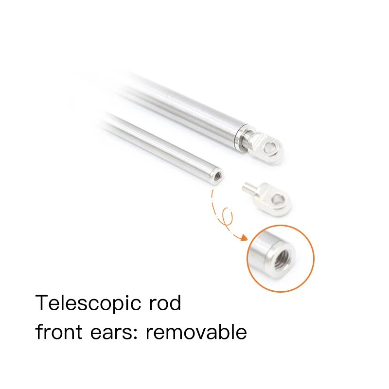
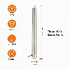
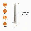
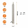
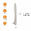
A KABASI tiny linear actuator shown as a fit reference. Review the tray guides and the actuator mounting drawing together.
Run the first sample in the instrument
The tiny linear actuator and compact 5 V linear actuator are starting points for fit and voltage review. Ask for the mounting drawing and loaded performance for the configuration under consideration. Check the compact electric linear actuator range if the first candidate misses the travel or envelope, and see the laboratory equipment actuator applications page for covers, shields and other motion roles.
Run the loaded tray through the actual sequence and log time, current, end position and any binding. Use the actuator sample testing checklist to record the sample configuration, conditions and acceptance criteria. If the tray only binds near one end, record the location and inspect guide alignment and cable movement before increasing thrust.
Send the rail layout, loading and presentation positions, available mounting space, measured startup force and target move time.