





Tiny Linear Actuator
Product model: KT0905-30L
Product material: 304 stainless steel + copper alloy
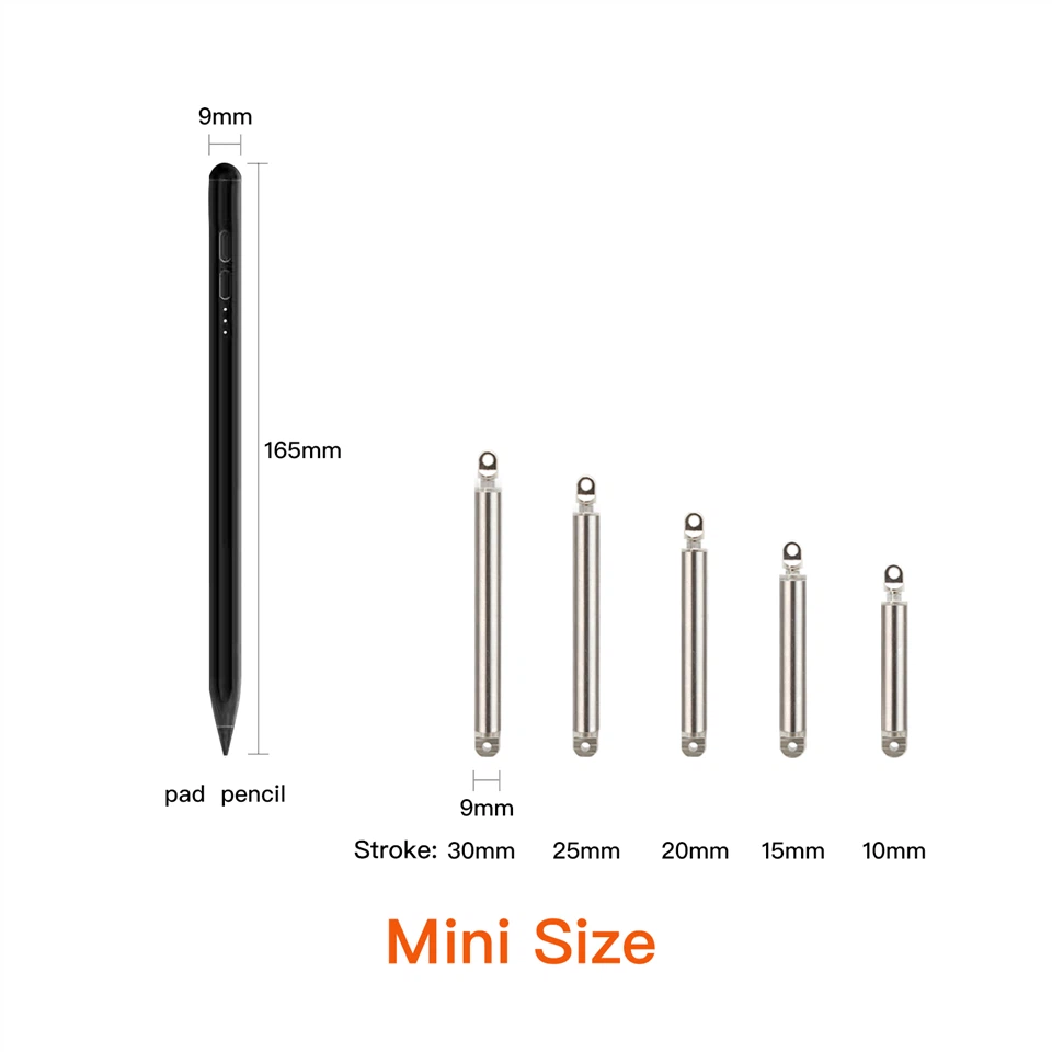
Stroke: 30mm (customizable)
Total length: 84mm
Push-pull force: 2.0KG
No-load push-pull speed: 2mm/s
Protection current: 0.2A
Rated voltage: 5V
Noise: ≤50dB
Protection level: IP56
Self-locking force: greater than 100N
Products Description
Where this rod belongs: the lift-and-lower outlet of a humidifier or an air purifier
A tiny linear actuator is best judged against a job rather than a data sheet, so take the outlet that rises out of the top of a humidifier or an air purifier. In standby the outlet sits flush with the cover; in use it has to stand clear of it, so that the mist or the air leaves the machine instead of washing across the cover surface. The part that performs the lift sits inside the housing - a 5 V DC push rod of the KT0905-30L type - with its rod coupled to the movable outlet and its body fixed to the frame.
Three features of the job make it awkward. The raised height has to repeat exactly, cycle after cycle, because the cover profile is what the outlet ends up working against. The raised position has to survive a supply failure, since a nozzle that slides back down brings a wet outlet into contact with the housing. And the assembly lives with mist, splash from filling the tank, dust drawn through the machine, and a room that has to stay quiet overnight.
What those demands ask of the rod
| The mechanism asks for | The figure that answers it |
|---|---|
| A raised height that never varies | 30 mm of travel ended by the limit board at both ends |
| Position preserved with the supply removed | 10 kg of resistance to back-driving in the screw drive |
| A lift that stays gentle | 2 mm/s, with 2.0 kg available across the whole stroke |
| A rail the appliance already provides | 5 V DC rated, with current limited to 0.2 A |
| Mist, filling splash and dust | IP56 sealing around a 304 stainless steel guide tube |
| Overnight use in a bedroom or a hotel room | Noise under 50 dB |
| Very little room behind the cover | 84 mm overall in a 9 mm / 5 mm tube package |
The same arrangement suits any product that has to uncover an opening by raising a part out of the housing and keep it there - diffusers, mist fans, small appliance covers. Where the moving part is a louver linkage or a damper instead, the vents and louvers application page covers that case, and the applications hub groups the rest.
Key specifications
| Parameter | Specification |
|---|---|
| Version | Thrust version (L): low speed, high force |
| Rated voltage | 5 V DC |
| Stroke | 30 mm (standard) |
| Stroke options in the same family | 10 / 15 / 20 / 25 / 30 mm; longer strokes by customization |
| Total length | 84 mm |
| Push-pull force | 20N |
| No-load push-pull speed | 2 mm/s |
| Full-load push-pull speed | 1.4 mm/s |
| Self-locking force | 100N |
| Protection current | 0.2 A |
| Noise | <50 dB |
| Protection level | IP56 |
| Duty cycle | 10% (long periods of repeated operation are not recommended) |
| End-of-stroke behaviour | Automatic stop at both end positions |
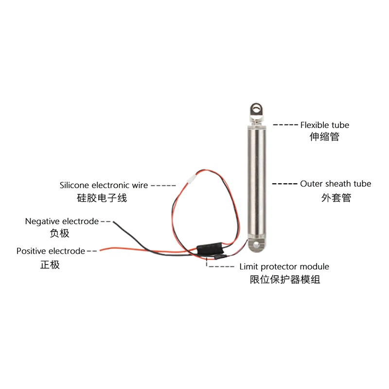
| Limit protection | External limit protection board (mounted outside the tube) |
| Outer tube diameter | 9 mm |
| Inner (telescopic) rod diameter | 5 mm |
| Guide tube material | 304 stainless steel |
| Duty | 10% |
- Position kept without power. Once the rod has moved, the copper alloy screw resists being pushed back up to 10 kg. Nothing has to stay energised to keep an outlet raised, and nothing drifts while the appliance sits in standby.
- Slow by design, with force in hand. 2 mm/s and 2.0 kg are a deliberate pairing. The moving part is carried rather than thrown, the movement stays quiet, and torque remains in reserve when a guide stiffens after a long idle period.
- Sealing chosen for wet work. The guide tube is 304 stainless steel and the screw is copper alloy, with IP56 sealing around the moving rod - a combination picked for mist, splash and dust rather than for a dry cabinet.
- Quiet enough to live with. Noise stays under 50 dB, so a lift at switch-on is not the event that identifies the appliance in a quiet room.
Control, Wiring and Direction
Electrically the rod is simple: two leads in, no signal out. Your controller sets direction by swapping the two leads, and the unit itself decides where travel ends.
| Controller action | Response of the rod |
|---|---|
| 5 V DC, one polarity | Travels out until the end-of-stroke cut-off acts |
| Supply removed | Stays in place, drawing no current |
| 5 V DC, polarity reversed | Travels back until the cut-off acts at the home position |
| Supply removed again | Stays at the home position |
Fitting It: Four Rules
Apart from a binding guide, almost every premature return of a small rod traces back to the way it was fixed. Four rules cover most of the cases.
Keep the work axial. The rod is built to push and pull along its own axis. A lever that presses across it, or a nozzle that is not guided, transfers load into the bearings and costs service life.
Fix the body to something that cannot move. The reaction to a 2.0 kg push has to reach a rigid surface. Slack in the cradle shows up as travel lost at the far end of the stroke.
Let the moving part carry itself. Horizontal and vertical mounting both work, but the weight of the outlet should rest on its own guide at the end of the stroke rather than hang on the rod.
Plan for the cut-off board and for the rod seal. The board forms part of the body's outer profile, so it needs clearance where it fits. Around the rod exit, keep run-off and abrasive residue away, so the sealing is not asked to hold back standing water.
Specifying Your Version
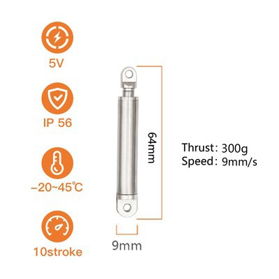
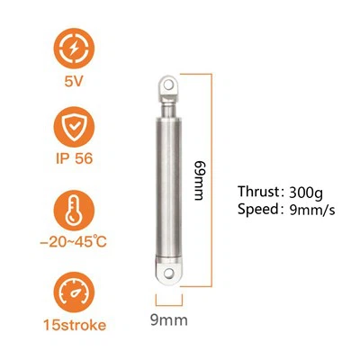
1 - Pick the character of the movement. This family offers two: the thrust version, which is what this page covers (2 mm/s, 2.0 kg), and the high-speed version (9 mm/s, 0.3 kg) for light parts that must move quickly. Choosing the wrong one of the two is the most common selection error, and it is worth ruling out first.
2 - Read the travel off your mechanism. Measure the distance the moving part must cover, not the distance the rod could provide. Members run from 10 mm to 30 mm across the KT0905 miniature actuator range. Take 30 mm when a part has to stand clear of a housing surface; shorter members suit catches, gates and small lids.
3 - Check what has to be held. Where a part must stay put with the supply removed, the 10 kg self-locking figure is the deciding number.
4 - Check the surroundings. The sealing, the stainless guide tube and the copper alloy screw suit humid, splash-prone and dusty products. For harsher conditions, see the stainless steel linear actuator range; other supply arrangements sit under DC linear actuator.
5 - Settle what we can change. Travel, force, voltage, lead length and connector are all open to specification, and OEM / ODM work is welcome - from a modified 30L to a new miniature push rod shaped around your own enclosure. Where the electronics are yours to specify, see linear actuator control; if you are still comparing drive principles, linear motor actuator sets out the alternative.
Symptoms and What to Look At
| Reported symptom | Usual origin | Action |
|---|---|---|
| The outlet no longer reaches the same height | The mount has shifted, or the guide has worn | Check the mounting face and the guide; end positions are set in the factory and do not drift by themselves |
| Uneven lift, or the rod sounds laboured | The moving part is loading the rod across its axis | Re-align the connection and let the outlet run on its own guide |
| Travel stops part-way through | Something in the guide is binding and current has reached the 0.2 A limit | Clear scale, mist residue and foreign material from the path |
| A film of residue where the rod leaves the body | Standing mist, dust or cleaning agent around the seal | Clean the area with a soft damp cloth, dry it, and keep abrasive cleaners away from the sealing |
| Erratic or dead operation | Lead polarity, a loose connection, or moisture at the connector | Confirm polarity and reposition the connector above the water line |
Who Makes It, and How It Is Checked
Tubes, screws, drives and cut-off boards for this range are produced and assembled in our own plant, which is why a change of stroke or force is a production instruction rather than a sourcing exercise. Units pass incoming material and motor checks, dimensional measurement, electrical and insulation testing, salt spray exposure and wire-bending before they are packed, all inside an ISO9001:2015 system. CE, RoHS and TUV certificates, plus more than 30 national patents, cover the range - see the certificate list. The factory has been building miniature actuators since 2015 and supplies equipment makers in over 60 countries; about us, our test equipment and why us add the detail.
What We Need in Order to Quote Without Guessing
Six answers remove the guesswork from a selection:
- The travel your mechanism has to cover, and the clearance you need at each end.
- The load at the far end, including a stiff guide, a return spring or a long idle period.
- How the moving part is guided, and where the rod connects to it.
- The supply available and the driver you intend to use.
- How many lifts per session, and how long the part stays in the raised position.
- What has to happen when the supply is removed.
Send those with a drawing, a CAD view or an annotated photograph, and the answer is usually a specific version rather than a range.
Frequently Asked Questions
Q: What kind of job suits a tiny linear actuator with this much travel?
A: Jobs where a small part has to move clear of a housing and stay there - an outlet lifting above a cover, a flap opening past a seal, a probe deploying, a cover standing off a compartment. Where the part only has to be released from a catch, a shorter member of the same family is usually the better fit.
Q: How much force can the KT0905-30L apply?
A: 2.0 kg, about 19.6 N, held across the whole stroke and not only at the outset, with 10 kg of self-locking resistance keeping that position afterwards.
Q: Will it run from the 5 V rail of my own board?
A: Yes. Rated voltage is 5 V DC and current is limited to 0.2 A. Leave headroom on the rail for the inrush a small motor takes at start-up, and swap the two leads through an H-bridge or two relays to change direction.
Q: Is any position sensing needed?
A: No. Both ends of travel are decided inside the unit, so nothing has to be added on the control side: no travel switch, no encoder, and no position routine to write.
Hot Tags: tiny linear actuator, China tiny linear actuator manufacturers, suppliers, factory, Dc Linear Actuator, linear actuator with manual override, electric servo actuator, Stainless Steel Linear Actuator, Ip56 Linear Actuator, Linear Motor Actuator
You Might Also Like


Send Inquiry