





Electric Lift Cylinder
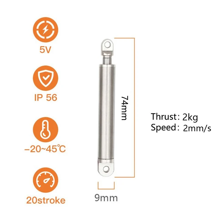
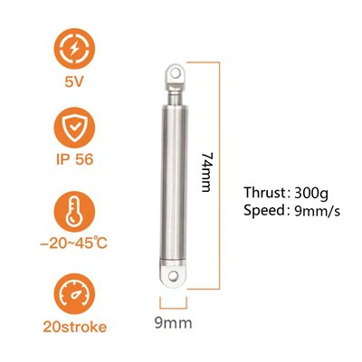
Product model: KT0905-20L
Stroke: 20mm (customizable)
Total length: 74mm
Push-pull force: 20N
No-load push-pull speed: 2mm/s
Protection current: 0.2A
Rated voltage: 5V
Self-locking force: greater than 100N
Products Description
An electric lift cylinder is easier to understand through one real appliance part than through a data table, so start with the module that opens the door of a dishwasher. On mid-range and premium machines the drying result depends on what happens in the last twenty minutes of the programme: the wash chamber is full of warm, humid air, and if the door stays shut that air condenses back onto the crockery. The appliance therefore releases the door for the final part of the cycle so the moisture can leave the chamber. The part that does the releasing is a small latch-and-push module built into the top edge of the door, and inside it sits a thrust-type actuator - a 5 V DC micro push rod like the KT0905-20L.
That module has three jobs, and each of them is harder than it looks:
- It has to hold a sealed door against a live wash chamber. During the wash the door is clamped by a latch; if that latch creeps, water and steam escape onto the kitchen floor. A module that only works while it is powered is not good enough.
- It has to open the door by a controlled amount, not throw it. The rod releases the latch and cracks the door open; the door then continues under its own weight. If the first push varies, so does the gap - and so does the drying result, cycle after cycle.
- It has to survive the environment it lives in. Condensate, detergent mist, kitchen grease and dust all sit around that mechanism, and the appliance is expected to be silent in an open-plan kitchen, often at night.
Position holding, a repeatable 20 mm of travel, sealed construction and low noise are the real design constraints here - which is exactly the set of problems the KT0905-20L was built around.
Product Parameters
| Parameter | Specification |
|---|---|
| Rated voltage | 5 V DC |
| Stroke | 20 mm (standard) |
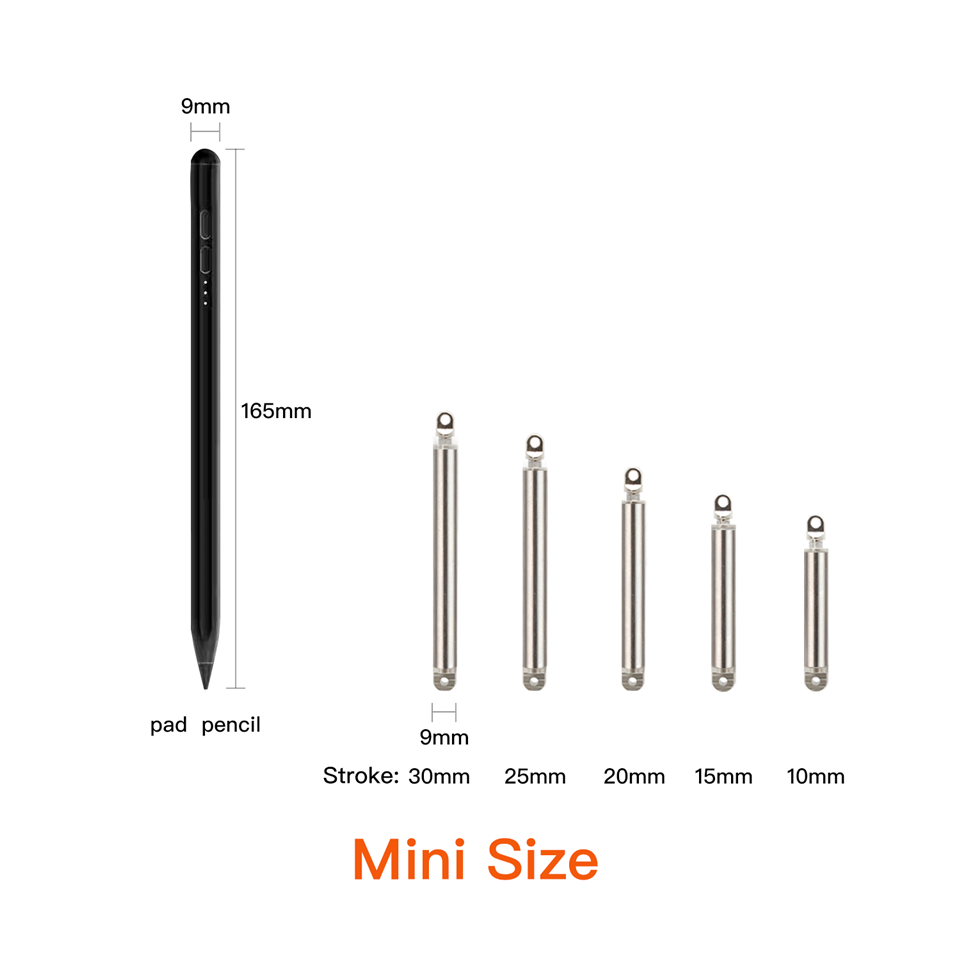
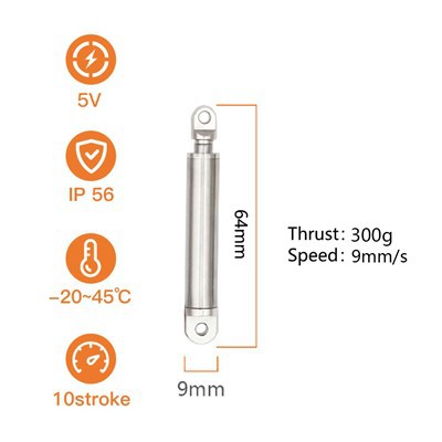
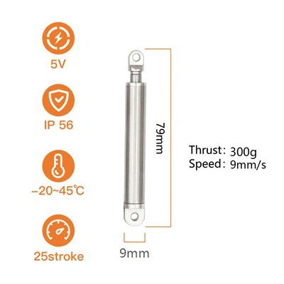
| Stroke options in the same family | 10 / 15 / 20 / 25 / 30 mm; longer strokes by customization |
| Total length | 74 mm |
| Push-pull force | 20N |
| No-load push-pull speed | 2 mm/s |
| Full-load push-pull speed | 1.4 mm/s |
| Self-locking force | 100N |
| Protection current | 0.2 A |
| Noise | <50 dB |
| Protection level | IP56 |
| Duty cycle | 10% (long periods of repeated operation are not recommended) |
| End-of-stroke behaviour | Automatic stop at both end positions |
| Limit protection | External limit protection board (mounted outside the tube) |
| Guide tube material | 304 stainless steel |
| Drive | Copper alloy lead screw (motor and screw, rotary-to-linear) |
| Wiring | Silicone electronic wire, positive and negative leads; direction set by reversing the polarity |
| Operating position | Horizontal or vertical, with the load guided in line with the rod |
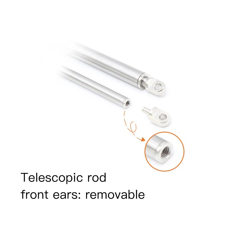
| Internal structure | Telescopic tube, outer tube and limit protection board |
From mechanism demand to specification
| What the module needs | KT0905-20L specification | What it delivers in practice |
|---|---|---|
| A sealed door that stays sealed, with or without power | 10 kg self-locking force | The latch holds mechanically; a power cut does not wet the kitchen floor |
| Just enough movement to release a latch and crack a door | 20 mm stroke (10–30 mm available in the same family) | A short, compact module that fits into the door edge profile |
| A repeatable opening, cycle after cycle | External limit protection board, automatic stop at both positions | The door opens by the same amount every time; no travel switch and no position programming in your harness |
| A release that does not slam the door | 2 mm/s no-load speed, 2 kg push-pull force | Controlled unlatching; force in reserve when the latch is stiff after standing |
| A supply shared with the appliance's own control board | Rated voltage 5 V DC, protection current 0.2 A | Runs from the board's 5 V rail; the 0.2 A protection current guards the motor if the mechanism jams |
| Condensate, detergent mist, kitchen dust | IP56 protection, 304 stainless steel + copper alloy | Moisture and dust stay out of the drive; the metal parts resist corrosion |
| A kitchen that is also a living room, at night | <50 dB noise | The release is heard as a soft click of the door, not as a motor |
| Limited space inside the door edge | 74 mm total length | Integrates into a compact housing without dictating the door design |
Product Features
- External limit protection board The limit protection board sits outside the tube, not buried in the drive train. It cuts the motor at both end positions before the mechanism can stall, which protects the motor and keeps the stroke repeatable from the first cycle to the last.
- A screw drive that holds position once the power is gone Self-locking force is 10 kg. The rod stays exactly where it was set with no current being drawn, so a latch stays engaged and a lever stays in position through a power failure - no separate holding brake, no re-homing on restart.
- Deliberate, low-speed motion with force in reserve The KT0905-20L converts its 5 V DC input into 2 mm/s of travel with 2 kg of push-pull force. That trade is deliberate in releasing, metering and positioning work: the load is moved under control rather than struck, and torque is still available when a mechanism is stiff after a long idle period.
- Sealed against steam, splash and dust IP56 protection is combined with a 304 stainless steel guide tube and a copper-alloy lead screw, so the drive keeps working in humid, splash-prone and dusty surroundings - the environment found around appliance doors, dispensers and covers.
- Quiet enough for a kitchen, a bedroom or a lobby Running noise stays below 50 dB, so the mechanism does not become the loudest part of the appliance it is fitted to.
- Current-limited against overload The 0.2 A protection current prevents motor burnout caused by overload or a jammed mechanism, and keeps the module inside the budget of a small control board.
- Compact 74 mm body At the 20 mm stroke the body measures 74 mm, which keeps integration simple in miniature equipment and inside door edges, covers and housings.
Duty Cycle and Cycle Planning
A push rod this size is a two-position device, not a continuous actuator, and the manual says so plainly: the working frequency is 10%, and long periods of repeated operation are not recommended. In practice that is generous for the applications the KT0905-20L is specified into, but the arithmetic is worth doing once before you design the mechanism.
| Quantity | Value | How it is arrived at |
|---|---|---|
| Stroke | 20 mm | Model specification |
| Time per stroke, no load | about 10 s | 20 mm ÷ 2 mm/s (calculated reference value) |
| Time per stroke, full load | about 14 s | 20 mm ÷ 1.4 mm/s (calculated reference value) |
| Permitted duty cycle | 10% | Manual specification |
| Rest required after a 10 s stroke | about 90 s | 10 s ÷ 10% = 100 s period, minus the 10 s of travel (calculated reference value) |
What that means in appliance terms: a dishwasher's door module runs one or two strokes per programme, so the duty limit is never approached. A mechanism that releases a shutter twenty times an hour is equally comfortable. The figure to respect is the one in the table - a push rod that is asked to run continuously will get hotter than it was designed to, whatever the load.
The same table is the reason the KT0905-20L is a poor candidate for a reciprocating motion (a pump, a stirrer, a wiping action) and a good candidate for position change: release, open, close, latch, hold.
What the External Limit Protection Board Does
The limit protection board is mounted outside the tube, on the body of the actuator, rather than buried inside the drive train. It is the part that ends the stroke, and it changes what you have to design around:
You get two defined positions, not a distance you have to measure. The board cuts the motor at both ends of the 20 mm stroke, so the mechanism has a home position and a working position without a hall sensor, an encoder or a travel switch in your harness.
The motor is protected, not sacrificed. Because the drive is cut before the rod reaches a hard stop, the motor is never left stalling against the mechanism - the failure mode that quietly kills small actuators.
It needs clearance in your housing. Because the board sits outside the tube, it adds to the footprint of the actuator on one side. Check that clearance at the design stage, before the tooling is cut, rather than after.
It is fixed at the factory. The end positions are a property of the unit. If your mechanism needs a shorter working stroke than 20 mm, tell us the figure and the stroke can be set or a shorter model specified - rather than trying to limit the travel mechanically in your own assembly.
Integration Checklist (before you design it in)
- Size the force against the worst case, with margin. 2.0 kg covers the release effort of a latch or a stiff flap when the mechanism is new. Add the extra effort that friction, a spring and a long idle period contribute, and consider whether a lever arm should be introduced.
- Keep the load in line with the rod. This is a micro actuator: a side load will shorten its life. Guide the door, latch or cover on its own path so the rod only pushes and pulls.
- Check the clearance around the limit protection board. It sits outside the tube. Confirm there is room for it where the actuator mounts.
- Plan the polarity and the drive current. Direction of travel is reversed by reversing the 5 V DC polarity. Your driver or H-bridge has to cover the 0.2 A protection current plus the consumption of your own electronics.
- Tell us the rhythm of your product. The duty cycle and the expected strokes per day decide whether this actuator or a beefier arrangement is right. Share the figures and we will confirm the version.
- Protect the seal when the module goes together. Keep abrasive residue and cleaning agents away from the rod exit, and check that the seal is correctly seated as the unit is fitted into the housing.
Quality Control, Certifications and the Factory
Every KT0905-20L is produced in our own plant rather than assembled from bought-in modules, and it is checked in-house under an ISO9001:2015 quality management system: incoming material and motor inspection, dimensional measurement, electrical and insulation resistance checks, salt spray corrosion testing and wire bending tests - so accuracy, motor performance, electrical reliability and corrosion resistance are verified before a unit is packed. The range carries CE, RoHS and TUV certification plus more than 30 national patents, and the certificates can be viewed on our certification page. Xiamen Kabasi Electric Co., Ltd. has manufactured miniature electric linear actuators since 2015 and exports to more than 60 countries and regions - see about us, testing equipment and why us.
Why Choose KABASI
The actuator is ours, not a bought-in module. The drive train, the tube and the limit protection board are developed and produced inside our own factory, so a change of stroke, speed or force is a production question rather than a sourcing one.
Customization is part of the standard offer. Stroke, thrust and voltage can all be adapted, and OEM / ODM projects are welcome - from a modified KT0905-20L to a new miniature push rod designed around your housing.
You buy from the factory that makes it. There is no intermediary layer between the drawing and the shipment, which keeps both the price and the lead time competitive.
The same actuators already run in more than 60 countries. Our miniature actuators are fitted in equipment built across more than 60 countries and regions.
Service you can plan around. Every enquiry is answered within 12 hours, products carry a one-year warranty with lifetime maintenance, and our engineers will help you select the version before you commit to a design.
Frequently Asked Questions
Q: How often can it operate?
A: The working frequency is 10% and long periods of repeated operation are not recommended. At 20 mm, one no-load stroke takes about 10 seconds, so allow roughly 90 seconds of rest between strokes if you intend to run it repeatedly. Appliance duties - a few strokes per cycle - sit far inside that limit.
Q: Why is the movement so slow?
A: Speed has been traded for force and control. 2 mm/s with 2 kg through the whole stroke lets the actuator release a latch or move a cover without impact, keeps the noise below 50 dB, and holds the current inside the 0.2 A protection limit. Where the movement must be quick and the load is light, the high-speed version is the one to specify.
Q: What is the difference between the KT0905-20L and the other members of the family?
A: Stroke and character. The 20L is a thrust version: 20 mm of travel, 2 mm/s and 2.0 kg, in a 74 mm body. Longer and shorter thrust versions run at the same speed, and the H version trades force for speed - 9 mm/s but 0.3 kg. Stroke, thrust and voltage can also be customized, and longer strokes than the standard list are available.
Hot Tags: electric lift cylinder, China electric lift cylinder manufacturers, suppliers, factory, electro hydraulic actuator, actuators pneumatic, electric jack screw actuator, electric lift actuators, Dc Linear Actuator, electric hydraulic linear actuator
You Might Also Like

Send Inquiry