HIDDEN PANELS · PORT COVERS · SMALL ENCLOSURES
A micro actuator is worth considering when your panel has a defined motion path, room for the complete drive assembly and a manageable push-or-pull load throughout the movement. A short visible movement does not necessarily mean a short actuator will fit.
Before choosing a model, establish how the panel clears the housing, what guides it and where the wires move. If the panel binds when the enclosure is assembled, increasing actuator force may damage the mechanism instead of fixing the fit.
|
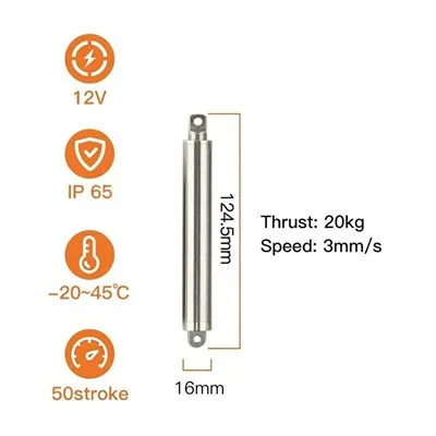
Product reference. Allow space for the body, moving rod, connections and wiring. |
Start with the panel path, not the actuator diameterTrace the panel from fully closed to usable opening. A flush panel may need to lift away from the trim before it can slide. A port cover may rotate successfully yet still block the plug or the user's fingers. These clearance problems must be solved in the mechanism. A straight slider can connect to an actuator along its travel direction. A hinged cover follows an arc, so the mounting arrangement needs pivots or a linkage that accommodates the changing angle. A lift-then-slide panel needs a guide, cam or linkage to create that sequence. If you only need to release a catch, size the drive for that release action. The spring or user may complete the opening. For scene examples, see electronics and smart home actuator applications. |

Reserve the space the assembly actually uses
Check the closed, partly open and fully open positions. The tightest clearance can occur halfway through the movement, especially when the actuator body pivots or a cable loop changes shape.
| Space to reserve | What gets missed |
|---|---|
| Actuator envelope | Retracted and extended dimensions, mounting hardware, connector projection and clearance around a pivoting body. Stroke is only the change in length. |
| Panel and linkage sweep | Trim overlap, hinge sweep, lever rotation, gasket contact and the space needed to insert a plug after opening. |
| Wiring and assembly access | Cable bend allowance, strain relief, screw access and a practical way to connect or replace the actuator after the housing is assembled. |
A wide panel pushed from one edge can twist in its guides. A hinge bracket that is slightly off-axis can pull the actuator rod sideways. Use the panel rails or hinge to carry the panel and constrain its motion, then connect the actuator so it supplies force along the intended path.
Avoid forcing the actuator and two rigid guides to establish competing paths. Mounting misalignment can turn a free-moving slider into a tight assembly. A suitable joint or deliberately controlled compliance can accommodate variation, but excess play may leave the visible panel loose.
Use model-specific side-load limits where documented. Do not assume the actuator rod can replace a guide or withstand a user pressing on the open panel.
A flush appearance creates a tolerance problem
The finished gap depends on more than actuator travel. Housing dimensions, guide clearance, hinge position, bracket location and gasket compression all contribute. Individually acceptable parts can combine to leave a cover proud, squeeze it against the trim or load the drive before motion begins.
With the drive safely disconnected, check the mechanism through its full movement in the assembled housing. Use the actual guides, seals and harness. This helps separate enclosure friction from an actuator performance issue.
| What you observe | Where to investigate first |
|---|---|
| It binds only after the screws are tightened. | Housing distortion, guide alignment, screw-induced preload or a trapped wire. |
| One edge reaches the trim first. | Panel skew, uneven guidance or an off-center drive connection. |
| It stops just before closing. | Gasket compression, latch engagement, cable folding or insufficient travel at the connection point. |
These observations identify likely checks; they do not establish the cause without examining the assembly.
Give moving wires their own spaceIf the hidden panel carries a display, sensor or charging interface, its harness moves with it. The actuator may also have a moving cable exit if its body pivots. Route both so they stay clear of the rod, hinge and closing seam throughout the stroke. Provide strain relief and a controlled flexing section. Follow the cable or flex-circuit supplier's bend requirements for the intended repeated movement; there is no universal bend radius for every harness. A cable loop that becomes taut near the open position adds load. A loop that folds into a guide can create an intermittent jam. Include the production harness in the mechanism check rather than adding it after the actuator has been selected. |
Product reference, not an installed panel assembly. |

Choose force and speed for the complete movement
Panel weight is only one part of the load. Add guide friction, seal compression, spring resistance and harness drag. On a hinged cover, the bracket position changes the mechanical advantage, so the hardest part of the stroke may be near the closed position.
Compare speed at the required load and supply voltage. Maximum force and no-load speed cannot be treated as simultaneous performance. Request a force-speed curve or loaded operating data for the exact configuration when available. Without it, opening time under load remains a sample question.
Judge noise with the enclosure closed
A motor that sounds acceptable on the bench can sound different when attached to a thin plastic shell. Mounting stiffness, panel resonance, guide rubbing and end contact all affect what the user hears.
Separate a steady motor or gear sound from a click at startup, rubbing during travel or a knock at closure. Each points to a different adjustment. Softer mounting may reduce transmitted vibration but can also change alignment and the closed-panel gap.
Compare samples at the same voltage, load, movement speed, mounting arrangement, measurement distance and background noise. State the intended use environment, such as a bedside device or desktop control. A standalone decibel value cannot establish that the finished product will be quiet.
Decide how the mechanism handles an obstruction
Treat normal end-of-travel stopping and unexpected blockage as separate events. Use an appropriate end-detection method, then define what happens if the panel meets an obstacle before reaching that position. Depending on the mechanism, the response may be to stop, reverse a limited distance or wait for user intervention.
Motor current can help detect abnormal resistance, but startup, seal compression and supply variation also affect it. Establish thresholds and timing using the assembled mechanism. Current limiting alone does not confirm panel position or provide validated finger-pinch protection. Avoid repeated automatic retries into an unresolved obstruction.
The distinction between current limiting and travel switches is also visible in Pololu's separate guidance on motor settings and limit-switch inputs. Controller capabilities must be confirmed for the hardware you use.
PWM does not automatically provide position feedback. If the panel must stop partway or confirm a closed state, specify the sensing and controller requirements. Also decide how a user or service technician accesses the mechanism after power loss.
A powered cover does not establish an IP rating
IEC 60529 classifies protection provided by enclosures. An actuator's component rating does not establish protection at your cover seam, gasket or cable entry. Any finished-product claim needs to cover the intended assembly and operating state.
Move to product comparison when the path is defined
Once the assembled panel moves without unexplained binding and you have identified the available space, start with the linear drives category. Compare exact configurations rather than choosing from a product name alone.
Use the 5V Linear Actuator and Tiny Linear Actuator pages as starting points for dimensions and sample discussion. Confirm stroke, mounted length, loaded speed, current and control interface for the configuration being quoted.
If the concept needs a compound path that is not yet guided, or there is no room for the drive and wiring, revise the mechanism first. An actuator sample is most useful when it answers a remaining fit or performance question.
Describe your panel before choosing a sample
Tell us what the panel exposes, how it moves, the available space and required opening. Include the guide or hinge arrangement, resistance if known, supply voltage, movement frequency, noise target and expected quantity. Mention moving wires and any binding in the assembled housing. Estimates are useful-identify which details are still undecided.
Discuss panel actuator selection