Size a vent louver actuator from the distance between its mounting pins over the full blade sweep and the force required at the weakest linkage angle. For a shared linkage, check the blades as a group. A measurement near the middle of travel can miss the highest load.
Mark the linkage in closed, mid-travel and open positions
Mark the fixed actuator mounting pin, the blade or lever pivot, and the moving actuator mounting pin. Measure the fixed-to-moving pin distance at the two intended end positions. Check mid-travel and any position where the linkage approaches a straight line. A direct linkage can gain or lose leverage as it turns, and the maximum or minimum pin distance can occur between the endpoints.
| Blade position | Measure or inspect | Common reason to check |
|---|---|---|
| Closed or just starting | Pin distance, force to break away and any seal preload. | Starting movement can require more force than moving through the rest of the sweep. |
| Partway through | Pin distance and the perpendicular distance from the lever pivot to the actuator's line of force. | A short lever arm increases the axial force required to turn the blade. |
| Fully open | Pin distance, body clearance, cable movement and the load in the return direction. | The mechanism needs room to finish and then reverse under load. |
For an early force estimate, divide the required torque about the lever pivot by the perpendicular distance from that pivot to the actuator's line of force. Use compatible units. A torque of 1 N·m and an effective lever arm of 0.020 m give an ideal axial force of 50 N. This is an illustrative geometry calculation. Check the actual linkage load and ask the supplier about the selected configuration.
Confirm travel and timing on the assembled linkage
Check that the rod and both mounts can follow the arc without binding. Measure actual opening and closing time at the intended voltage and with the expected spring, seal, blade and pressure loads. Where airflow or wind can oppose motion, include the operating condition that the equipment has to meet. Define the blade position required when power is lost and check what the assembled linkage actually does.

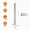
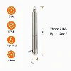
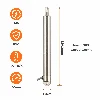
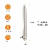
The KABASI long-stroke ventilation actuator is a candidate to review once the required pin distances and loaded move time are known.
For a longer mounting envelope, compare the long-stroke ventilation actuator with the 24 V tubular actuator. Use the linear actuator range to review other candidates. The vent and louver applications page covers blade bars, flaps and hinged covers. For the broader fit and load checks, see the industrial actuator selection guide.
Send a sketch with the blade pivot and both actuator pins marked. Include open and closed angles, measured load or torque if available, supply voltage and target travel time.
Share Your Louver Linkage Drawing