





24Vdc Linear Actuator
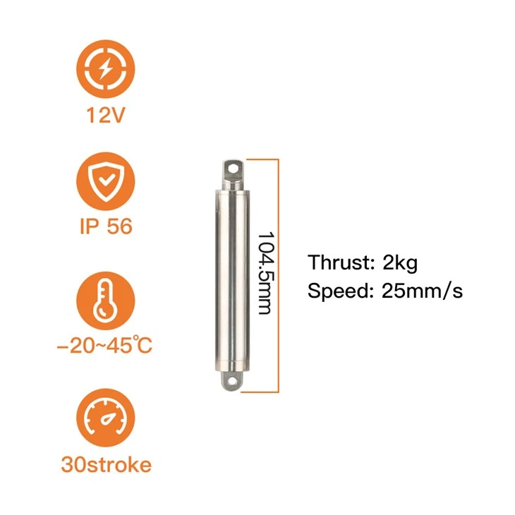
Product model: KT1610-30-2KG
Stroke: 30mm (customizable)
Total length: 104.5mm
Push-pull force: 20N
No-load push-pull speed: 25mm/s
Protection current: 0.32A
Rated voltage: 24V (or 12V)
Product Introduction
The 24Vdc Linear Actuator is built on the 16 mm KT1610 platform: a 304 stainless steel outer tube and rod, a T5 stainless lead screw running in a copper alloy nut, and an N30 all-metal reduction gear set, inside an IP56 sealed housing. The 2 mm lead screw is the standard build and produces the 25 mm/s no-load speed above, with 18 mm/s under full load, while static self-locking stays at more than twice the rated thrust - so the jaws hold the position they were commanded with no current in the motor. Protection current is 0.32 A at 24V DC, low enough to be switched straight from the cell's existing 24 V rail, and the external limit protection board stops the rod automatically at both ends of the stroke.
Where the Actuator Sits in the Gripper
An electric gripper is a linkage, and the actuator is its input. How far the jaws open, how hard they close and how fast they cycle are all set by that one linear input, so it is worth reading the mechanism before the datasheet:
| Gripper requirement | What sets it | This configuration |
|---|---|---|
| Jaw opening | actuator travel ÷ linkage ratio | 30 mm of travel; 15 mm of jaw movement through a 2:1 linkage |
| Grip force at the fingers | rod thrust × linkage advantage, split between the two jaws | 20 N at the rod - 40 N through a 2:1 linkage, before friction losses |
| Fastest open-and-close move | travel ÷ rod speed | ≈ 2.4 s unloaded / ≈ 3.3 s fully loaded, for the full 30 mm |
| Holding the grip after E-stop | static self-locking with no current | greater than 2× rated thrust (> 4 kg / 40 N) |
| Supply the cell has to switch | voltage and current | 24V DC standard at 0.32 A; 12V DC available on the same body |
| Fitting the drive inside the gripper body | envelope of the unit | 16 mm outer tube diameter; 104.5 mm retracted / 134.5 mm extended |
Technical Specifications
| Parameter | Specification |
| Static Self-Locking Force | Greater than 2× rated thrust (more than 4 kg / 40 N) |
| Stroke | 30 mm (this configuration); 10 / 20 / 30 / 50 / 100 mm standard, longer strokes on request |
| Lead Screw Lead | 2 mm (standard) / 4 mm (high-speed option) |
| No-Load Speed | Up to 25 mm/s (standard) / up to 50 mm/s (high-speed option) |
| Full-Load Speed | 18 mm/s (standard) / 32 mm/s (high-speed option) |
| Protection Current | 0.32 A at 24V DC / 0.64 A at 12V DC |
| Duty Cycle | Intermittent, approx. 10%; auto power-off at end of stroke |
| Operating Temperature | −45 °C to +60 °C |
| Retracted Length | 104.5 mm (30 mm stroke build) |
| Extended Length | 134.5 mm (30 mm stroke build) |
| Outer Tube | 16 mm outer tube diameter / 10 mm rod diameter |
| Mounting Base | Side-mounted base: round-hole (standard) or slotted, for flexible cable routing |
| imit Protection | External limit protection board, auto power-off at both ends |
| Service Life | 8000 cycles |
product key technologies

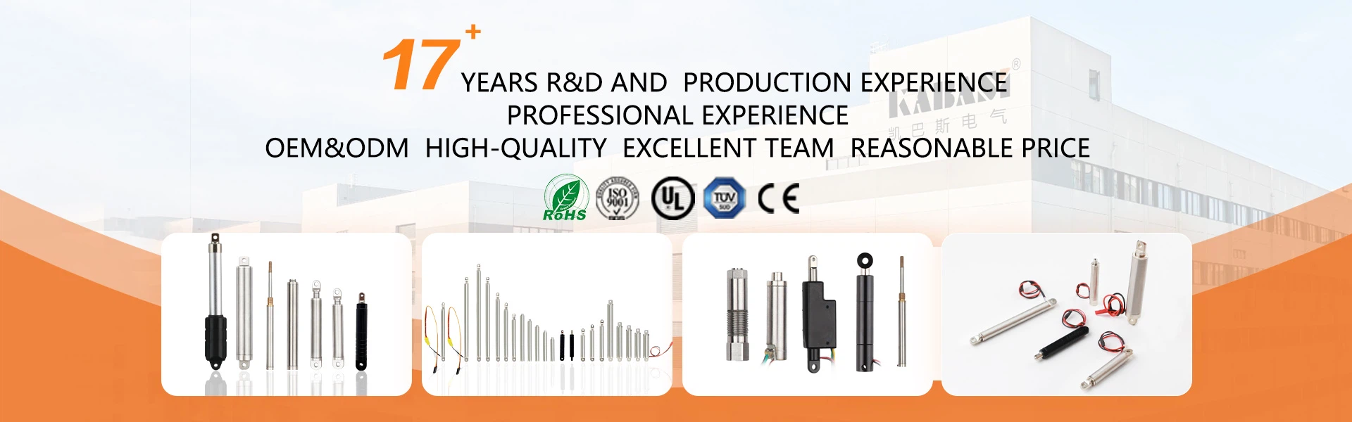
Five units of the family photographed together, from the longest stroke to the shortest. The 30 mm build on this page is the second-shortest of that group, and the point of the image is the constant: every stroke length keeps the same outer tube diameter, so a gripper design that has to change stroke does not have to change its mounting or its pin positions.
The front ear is machined from 304 stainless steel, the same grade as the outer tube, and carries the Ø4.0 mm hole that takes the pin linking the rod to the gripper's input lever. Both ends of the unit use the same front ear arrangement, so the gripper body and the lever need one pin each and no separate bracket.

Application Scenario
Parallel-jaw electric grippers on pick-and-place and sorting cells. In robotics and automation builds, a small electric gripper is usually two jaws driven from one linear input, and the 30 mm stroke on this page is the input side of that linkage: the rod extends, the input lever turns, the jaws separate, the cell indexes the arm, the rod retracts and the jaws close on the next part. The unit is mounted inside the gripper body, so the 16 mm outer tube is what has to fit - not the stroke. Parts that are light and easily marked suit a 20 N rod thrust, because the closing force that reaches the fingers can be dialled by the linkage rather than by a larger actuator, and the static self-locking hold means the part stays gripped if the cell is stopped mid-transfer.
A gripper is only one of the mechanisms this platform is used for. For the other equipment types this actuator family is built into, see the applications index.
Certifications, Testing and Warranty
The units are built in our own Xiamen factory under an ISO 9001 quality system, supplied with a CE declaration and RoHS documents, and covered by more than 30 national patents published on the certification page. Each production batch is verified on the six in-house test stations listed on the testing equipment page, the actuators ship factory-direct with a minimum order of one piece for prototype evaluation, and every unit carries a 6-month warranty against manufacturing defects - see why customers work with KABASI.
Frequently Asked Questions
Q: Is 20 N of thrust enough for my gripper?
A: Work it out from the linkage: multiply the force the fingers have to apply by the linkage ratio, and that is the thrust the rod has to supply. If the number lands above 20 N, the same 16 mm platform is built in 8 kg (80 N) and 20 kg (200 N) versions - send the linkage drawing, the part weight and the required jaw opening, and we will size the configuration for you.
Q: Can it be switched from the robot controller instead of a separate driver?
A: Yes. The unit is a plain two-wire DC motor with no internal controller, drawing 0.32 A at 24V DC. Direction follows the polarity of the two wires, so a reversing relay pair or a small H-bridge module in the cell cabinet is all the drive it needs, and the rod speed can be varied with PWM where the controller supports it.
Q: Does the gripper keep holding the part if the power is cut?
A: Yes. Static self-locking is greater than twice the rated thrust, so the rod holds its position with no current in the motor, and the jaws keep the grip they had at the moment the supply dropped. If the cell is required to release the part on power loss instead, that has to come from the gripper linkage or a return spring, not from the actuator.
Put This Actuator On Your Gripper Drawing
Send the linkage layout, the required jaw opening and the part weight. We will confirm the stroke, the pin positions and the thrust for your configuration, and issue a drawing with the quotation.
Related Selection
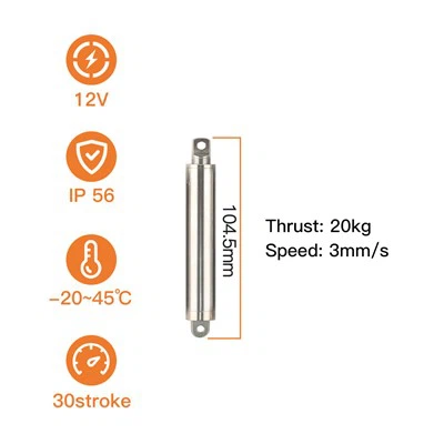
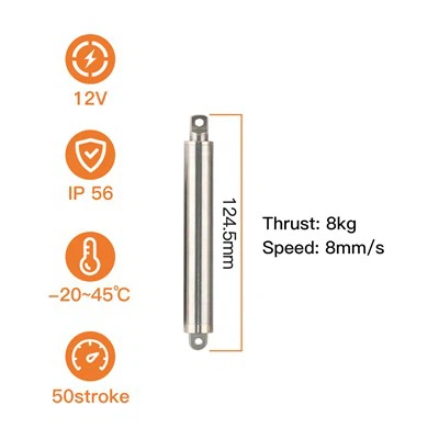
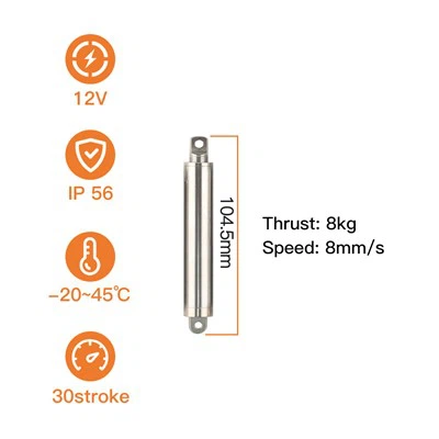
- Need more force in the same 16 mm body? See the 8 kg compact actuator or the 20 kg high-thrust actuator.
- Starting from the mechanism rather than the model? Browse applications by mechanism or the full product range.
- Need the platform's measured curves and material analysis? Read the KT1610 engineering audit.
Hot Tags: 24vdc linear actuator, China 24vdc linear actuator manufacturers, suppliers, factory, telescopic pneumatic cylinder, remote control linear actuator, heavy duty actuator, quiet linear actuator, servo actuator, acme screw linear actuator
Previous
Actuator 24VYou Might Also Like



Send Inquiry