





Linear Actuator 24V
Product model: KT1610-20-2KG
Stroke: 20mm (customizable)
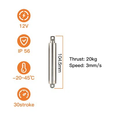
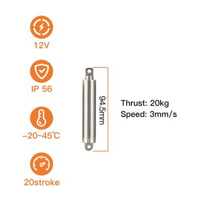
Total length: 94.5mm
Push-pull force: 20N
No-load push-pull speed: 25mm/s
Protection current: 0.32A
Rated voltage: 24V
Product Introduction
Instrument projects screen a Linear Actuator 24V 20mm on three things. The first is whether the head stays where it was put: the measuring position has to repeat from part to part - which in this arrangement comes from a reference stop in the fixture rather than from anything the drive measures - and the head has to stay there with nothing energised, meaning no holding current, no heat sitting beside the optics, and no drift when the instrument is switched off between measurements. The second is whether the drive keeps out of the measurement's way: quiet in operation, sealed against the dust and humidity of an enclosure interior, and small enough in diameter that the layout does not have to be redrawn around it. The third is how much the instrument has to add in order to use it: the rail already inside the cabinet can switch it, direction is set by two lead wires, and there is no controller, no encoder and no separate supply to package next to the head. A head that moves only a few times a day still has to move for years, which is why the drivetrain is metal rather than plastic, and where an instrument needs it in position faster than a normal measurement cycle asks for, the same body is built with a faster screw without changing the envelope, the travel or the mounting. The numbers behind all of it are in the three tables below.
Technical Data
- Stroke and Travel Data
| Parameter | Specification |
|---|---|
| Stroke, This Build | 20 mm; 10 / 20 / 30 / 50 / 100 mm standard, longer strokes on request |
| Time per Stroke | ≈ 0.8 s no-load / ≈ 1.1 s full-load, each direction |
| Retracted Length | 94.5 mm |
| Extended Length | 114.5 mm |
| Static Self-Locking Force | More than 2× rated thrust (over 4 kg / 40 N) |
| End-of-Stroke Protection | External limit protection board, auto power-off at both ends |
- Drive and Control
| Parameter | Specification |
|---|---|
| Model Number | KT1610-20-2KG-24V |
| Rated Voltage | 24V DC standard; 12V DC available on the same body |
| Duty Cycle | Intermittent duty, about 10%; the motor cuts out at each end of the stroke |
| Rated Thrust / Pull Force | 2 kg (20 N) |
| No-Load Speed | Up to 25 mm/s on the standard build; up to 50 mm/s on the high-speed build |
| Full-Load Speed | 18 mm/s on the standard build; 32 mm/s on the high-speed build |
| Screw Lead | 2 mm as standard, 4 mm on the high-speed build |
| Protection Current | 0.32 A at 24V DC / 0.64 A at 12V DC |
- Construction and Interface
| Parameter | Specification |
|---|---|
| Materials | Copper alloy drivetrain parts with a 304 stainless outer tube and rod |
| Outer Tube | Ø16 mm tube, Ø10 mm rod |
| Lead Screw | T5 stainless screw with a nickel-plated copper alloy nut |
| Reduction Gearing | N30 gear set, all metal |
| End Fitting | Front ear at both ends, 304 stainless steel |
| Mounting Pin Hole | Ø4.0 mm |
| Mounting Base | Side-mounted: round-hole as standard, slotted version available |
| Sealing | IP56 |
| Noise | < 60 dB |
| Ambient Range | −45 °C to +60 °C |
| Rated Life | 8000 cycles |
Key Features
20 mm of travel inside a 16 mm body. The stroke is built into the same envelope as the rest of the family, so a longer build costs length rather than width - the pins, the guide and the cable route stay where the drawing puts them.
20 N of thrust, with room to move up. The 2 kg build covers light, guided loads; if the load or the seal turns out heavier, the 8 kg and 20 kg builds use the same 16 mm outer tube and the same mounting.
Two speeds from one platform. A 2 mm screw gives up to 25 mm/s no-load and 18 mm/s at full load; the 4 mm screw version runs up to 50 mm/s and 32 mm/s when a sequence has to be faster.
Holds its position with nothing energised. Self-locking holds more than twice the rated thrust with the motor unpowered, so the load stays where it was put: no holding current, no heat to dissipate, and no drift when the supply is switched off.
Switched straight from a 24 V rail. 0.32 A at 24V DC and no controller to add - the two lead wires set the direction of travel by their polarity, and an external limit protection board cuts the motor at each end of the stroke, so the unit needs no encoder and no separate supply.
Sealed, quiet and all-metal. IP56, below 60 dB in operation, and a drivetrain with no plastic in it - 304 stainless tube and rod, T5 stainless screw, nickel-plated copper alloy nut, N30 gear set - rated for an 8000-cycle service life.
What Can Be Specified at Order
| Option | Available change |
|---|---|
| Voltage | 24V DC as standard; 12V DC available on the same body |
| Stroke | 20 mm on this build; 10 / 20 / 30 / 50 / 100 mm standard, longer on request |
| Lead wire and connector | Length and termination set for the route through the enclosure and along the moving guide |
| Thread | External or internal, cut to match the mating part - give us the size and the direction |
| Ear geometry | Front ear machined to suit the load carrier and the mounting pin |
| Base | Round-hole side mount, or a slotted base where the cable needs adjustment room at assembly |
| Screw lead | 2 mm as standard, 4 mm on the high-speed build |
| End-of-stroke protection | External limit protection board, set to your stroke |
| Speed control | Optional PWM drive board, for controllers that ramp the movement instead of switching it |
Typical Application
The movement this build is asked for most often is a sensing head that travels between a protected rest position and a working position in front of an optical or sensor instrument: the load rides in its own guide, the rod supplies travel and a modest push, and the self-locking hold keeps whichever of the two positions it was given when the machine is powered down. Other equipment types this platform is built into are listed in the mechanism index.
Documentation, Testing and Warranty
A prototype order is normally supplied with a CE declaration and RoHS documents for the units, together with the dimensional drawing of the configuration you ordered. What we hold is set out on the certificate and document list; the tests that sign the units off before shipment are the ones performed on the six stations each batch runs through; and if the project calls for a supplier audit rather than a document set, start from how the units are built in Xiamen. Units come direct from our own factory, which works to an ISO 9001 quality system; orders start at a single piece for evaluation, and each unit is warranted for six months against manufacturing defects.
Frequently Asked Questions
Q: How do I know whether 20 mm is the right stroke?
A: Add up three distances: the travel the load needs between its rest position and its working position, the breakaway the rest stop and any seal take up, and the margin you want between the load landing on its stop and the rod running out of travel. If that total lands above 20 mm, the same 16 mm body is offered in 30, 50 and 100 mm strokes, with longer strokes on request - send the drawing and the working position and we will confirm the stroke against it.
Q: The unit holds its position for hours between cycles. Does anything get warm?
A: No. At both ends of the stroke nothing is energised - the screw holds the position by itself - so there is no holding current to turn into heat, and the unit draws nothing at all between movements. The 10 % duty budget applies to the time it is actually moving, a fraction of a second per cycle, not to the hours it spends sitting in one position.
Q: What happens to the load if the supply is cut?
A: It stays where it was. The screw holds more than double the rated thrust on its own, so nothing has to be energised to keep the rod where it was told to stay, and neither position drifts when the supply drops. A machine that has to move the load back on power loss needs a return spring or a linkage to do it; the actuator will not release by itself.
Hot Tags: linear actuator 24v, China linear actuator 24v manufacturers, suppliers, factory, remote control linear actuator, high load linear actuator, aerospace linear actuator, worm drive actuator, belt driven actuator, smallest pneumatic cylinder
Previous
24Vdc Linear ActuatorNext
24V ActuatorYou Might Also Like



Send Inquiry