




24V Actuator
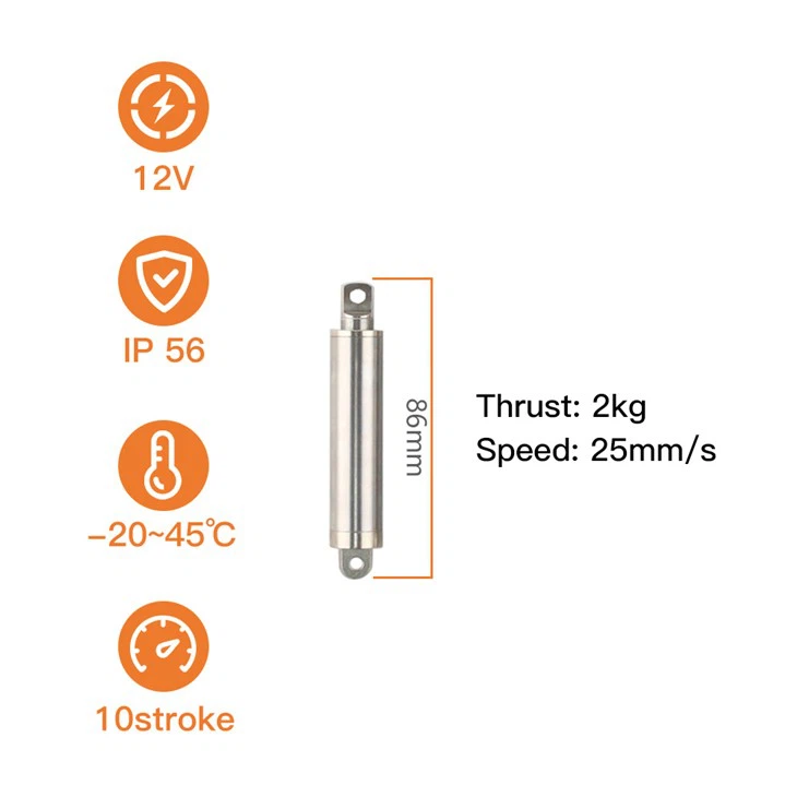
Product model: KT1610-10-2KG
Product material: 304 stainless steel + copper alloy
Stroke: 10mm (customizable)
Total length: 86mm
Push-pull force: 20N
No-load push-pull speed: 25mm/s
Protection current: 0.32A
Rated voltage: 24V (or 12V)
Product Introduction
The 24V Actuator 10mm build is only one of the three parts in this finger mechanism, and the other two decide what it produces. The finger link is carried on the knuckle shaft, the lever is fixed to that shaft, and the rod is pinned to the lever. Travel in, angle out - which is why the same 10 mm build produces a different curl on every hand, and why the useful first question is the lever radius rather than the model number. Force travels the same path: the 20 N at the rod becomes torque at the knuckle and then force at the fingertip, scaled by the two lever arms. The finger's own guide or stop carries any load across the joint, and the pose it reaches is set by a mechanical stop in the hand, not by anything the actuator measures.
Where the 10 mm of Travel Goes in a Finger Joint
| What the finger needs | What sets it | This configuration |
|---|---|---|
| Knuckle angle per stroke | stroke ÷ lever radius on the knuckle shaft | 10 mm of travel; about 38° through a 15 mm lever |
| Torque at the knuckle | rod thrust × lever radius | 20 N × 15 mm ≈ 0.30 N·m |
| Force at the fingertip | knuckle torque ÷ distance from the joint | ≈ 5 N at 60 mm out, before linkage friction |
| Fastest full curl | stroke ÷ rod speed | ≈ 0.4 s unloaded / ≈ 0.56 s at rated load, each direction |
| Holding a pose with the power off | static self-locking, no current | more than 2× rated thrust (over 4 kg / 40 N) |
| What the hand's board has to switch | voltage and current | 24V DC standard at 0.32 A; 12V DC on the same body |
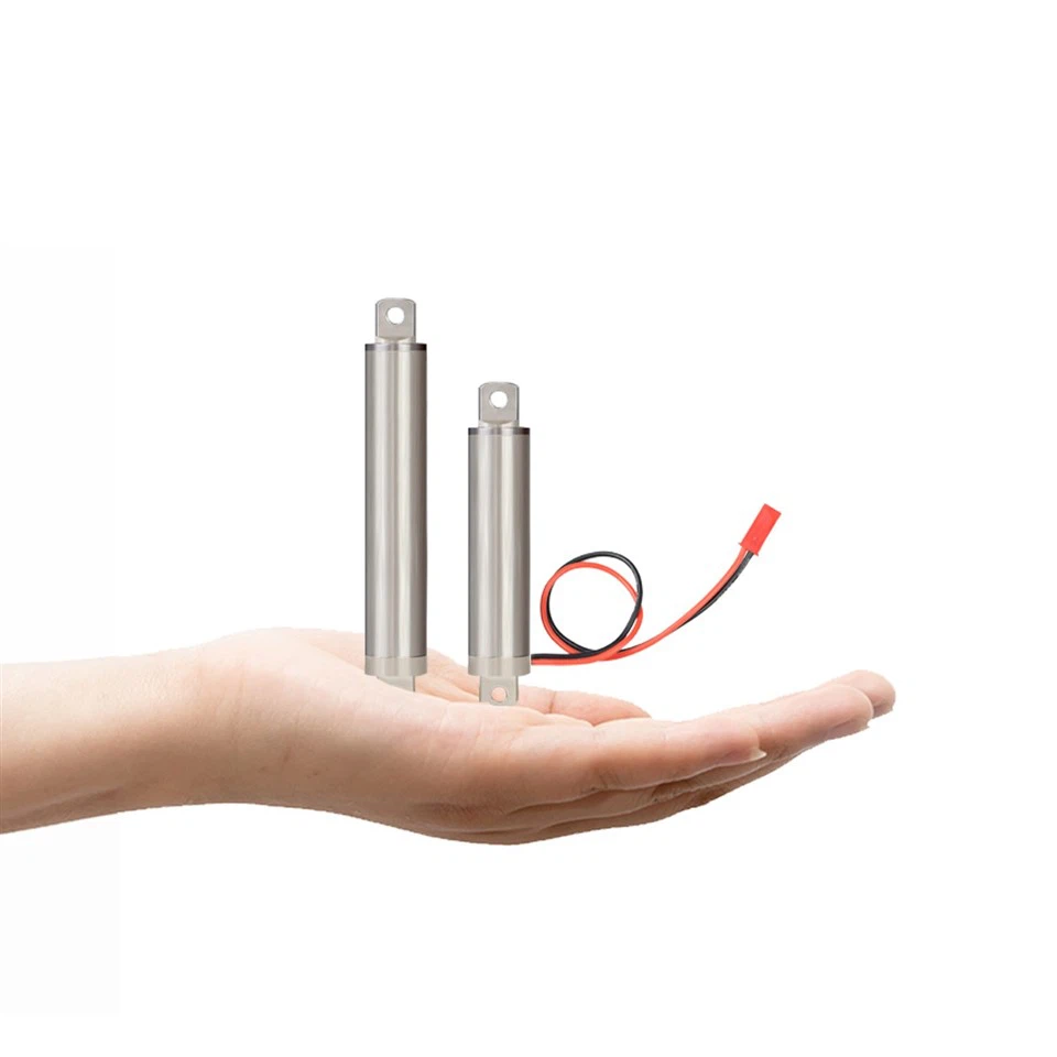
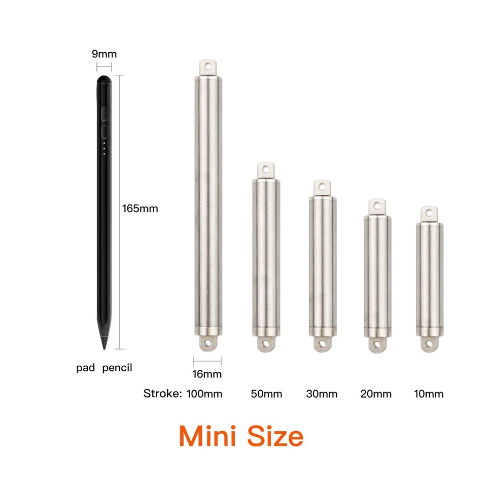
| Fitting the drive into the palm or finger base | envelope of the unit | 16 mm outer tube; 84.5 mm retracted / 94.5 mm extended |
Technical Specifications
| Parameter | Specification |
|---|---|
| Rated Voltage | 24V DC standard; 12V DC available on the same body |
| Rated Thrust / Pull Force | 2 kg (20 N) |
| Stroke | 10 mm (this build); 10 / 20 / 30 / 50 / 100 mm standard, longer strokes on request |
| Retracted / Extended Length | 84.5 mm / 94.5 mm on this 10 mm build |
| No-Load Speed | Up to 25 mm/s standard; up to 50 mm/s on the high-speed build |
| Full-Load Speed | 18 mm/s standard; 32 mm/s on the high-speed build |
| Time per Stroke | ≈ 0.4 s no-load / ≈ 0.56 s full-load on the standard build, each direction |
| Screw Lead | 2 mm standard; 4 mm on the high-speed build |
| Static Self-Locking Force | More than 2× rated thrust (over 4 kg / 40 N) |
| Protection Current | 0.32 A at 24V DC / 0.64 A at 12V DC |
| Motor and Control | Brushed DC, two lead wires; direction is set by polarity; no controller built in |
| Speed Adjustment | Optional PWM drive board where the hand's controller ramps the movement |
| Position | Set by the mechanical stop in the hand and by the end-of-stroke cut-out; no encoder |
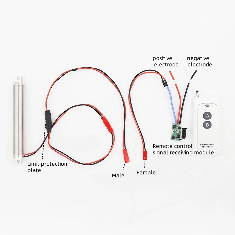
| End-of-Stroke Protection | External limit protection board, auto power-off at both ends |
| Duty Cycle | Intermittent, about 10%; the motor cuts out at each end of the stroke |
| Core Materials | 304 stainless steel outer tube and rod; copper alloy drive parts |
| Outer Tube | Ø16 mm tube / Ø10 mm rod |
| Mounting Pin Hole | Ø4.0 mm |
| Mounting Base | Side-mounted, round-hole as standard; slotted version available |
| Ingress Protection | IP56 |
| Noise | < 60 dB |
| Operating Temperature | −45 °C to +60 °C |
| Service Life |
8,000 cycles |
Key Features
- 10 mm of travel inside the same 16 mm body. The stroke is built into the envelope the rest of the family uses, so a hand that moves to a longer finger stroke does not have to redraw its palm, its pin positions or its cable route.
- 20 N at the rod, with room to move up. The 2 kg build covers a light finger link; if the finger turns out heavier or the return spring stiffer, the 8 kg and 20 kg builds use the same 16 mm outer tube and the same mounting.
- Two speeds from one platform. The standard 2 mm screw curls the finger in about 0.4 s; the 4 mm screw build does the same 10 mm in about 0.2 s where a demonstration sequence has to be quicker.
- Holds the pose with nothing energised. Self-locking holds more than twice the rated thrust with the motor unpowered, so a pose set during a demonstration stays set after the supply is switched off - no holding current, no heat, and no drift while the hand sits on a bench.
How It Compares
| What the finger has to fit | KT1610-10-2KG | Actuonix L12-10-210 |
|---|---|---|
| Body and mount | Ø16 mm round outer tube, Ø4.0 mm front ear at both ends - pins straight into printed lugs, no bracket, no adapter | Two brackets and #8-32 hardware have to be designed into the same space |
| Harness and control | 2 wires, direction by polarity; no controller, no encoder, no extra board | -P needs a 5-wire harness and an external control board; -I runs six wires to an on-board controller |
| Stroke choice in one body | 10 / 20 / 30 / 50 / 100 mm, longer on request | 10 / 30 / 50 / 100 mm |
| Time for one 10 mm curl | Up to 25 mm/s - about 0.4 s | 6.5 mm/s at the 210:1 gearing - about 1.5 s |
| Supply from the hand's rail | 24V DC standard, 12V DC on the same body, 0.32 A | 6V or 12V DC only (max input 13.5V) - a 24 V hand needs a converter board |
| Sealing | IP56 | IP54 |
| Working range | −45 °C to +60 °C | −10 °C to +50 °C |
| Prototype quantity | From one piece | 500 pieces minimum for customizations |
Installation and Use
- Mount. Fix the unit by its front ears through the Ø4.0 mm holes, pin the rod end to the knuckle lever, and keep the thrust line parallel to the axis - the finger's guide carries side load, not the rod.
- Set the stops. The curl and straight positions come from mechanical stops on the finger link, and the rod must reach them before its own travel runs out; the external limit protection board cuts the motor at both ends.
- Wire and test. Two lead wires: one polarity retracts, the other extends, and a relay pair or H-bridge on the hand's board is the whole drive. Jog it unloaded, check the angle at each end, then load the finger and confirm the pose holds with the supply off.
- Duty and care. Around 10% duty - one 0.4 s stroke needs a cycle period of at least 4 s. Wipe the tube and rod dry, keep the wire port dry, and do not use the unit as a structural support or as the mechanism's end stop.
our company
Founded in 2015, our company has over 10 years of experience specializing in the research, development, and production of miniature electric linear actuators and electric actuator systems.

Documentation, Testing and Warranty
Units are built in our own Xiamen factory under an ISO 9001 quality system and are supplied with a CE declaration and RoHS documents for the configuration you order. Certificates, patents and the document list are published on the certification page; the tests each production batch runs through are listed on the testing equipment page; and if your project needs a supplier review rather than a document set, start from why customers work with KABASI. Units ship factory-direct, orders start at a single piece for evaluation, and every unit carries a 6-month warranty against manufacturing defects.
Frequently Asked Questions
Q: Is 10 mm of stroke enough to curl a finger?
A: Work it out from the lever: divide the stroke by the radius of the lever on the knuckle shaft to get the angle, so 10 mm through a 15 mm lever is about 38°, and the same 10 mm through a 30 mm lever is about 19°. If your drawing needs more angle than the lever radius allows, the same 16 mm body is built in 20, 30, 50 and 100 mm strokes. Send the finger drawing with the lever radius and we will confirm the stroke against it.
Q: Does the finger keep its pose when the power is switched off?
A: Yes. Static self-locking holds more than twice the rated thrust - over 4 kg - with no current in the motor, so the pose stays where it was commanded and nothing has to stay energised to hold it. A hand that has to open by itself when the supply drops needs a return spring or a linkage to do it; the actuator will not release on its own.
Q: Can the hand's controller switch it directly, and how fast can it cycle?
A: Yes. It is a plain two-wire DC motor drawing 0.32 A at 24V DC, so a reversing relay pair or a small H-bridge on your board drives it, and a PWM output can vary the speed where the controller supports it. One 10 mm stroke takes about 0.4 s unloaded. Because the duty cycle is about 10%, allow a cycle period of at least 4 s per actuator - roughly 3.6 s of pause between movements - and the unit can also be ordered with a 4 mm screw lead when a demonstration sequence has to run faster.
Related Selection
- Need a longer stroke in the same 16 mm body? See the 20 mm 24V actuator or the 30 mm 24Vdc actuator.
- Need more force at the rod? See the 8 kg compact actuator or the 20 kg high-thrust actuator.
- Starting from the mechanism rather than the model? Browse applications by mechanism or the full product range.
Hot Tags: 24v actuator, China 24v actuator manufacturers, suppliers, factory, manual linear positioner, 3 inch linear actuator, 600mm linear actuator, 8 linear actuator, linear actuator without motor, 1 ton linear actuator
Previous
Linear Actuator 24VNext
Linear Motor 12VYou Might Also Like



Send Inquiry