





12V Actuator Linear
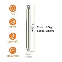
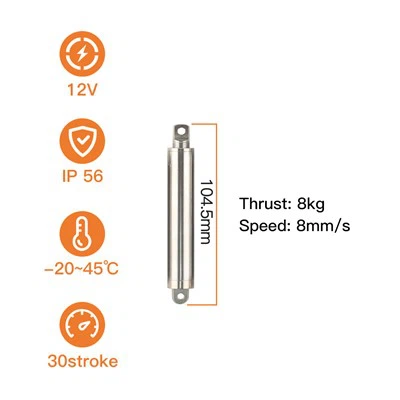
Product model: KT1610-100-8KG
Stroke: 100mm (customizable)
Total length: 174.5mm
Push-pull force: 80N
No-load push-pull speed: 8mm/s
Protection current: 0.64A
Rated voltage: 12V (or 24V)
Product Description
The 12V actuator linear unit on this page is the KT1610-100-8KG-12V: a 16 mm 304 stainless steel outer tube with a 10 mm rod, an all-metal screw drive and gear train, rated 8 kg (80 N) over a 100 mm stroke. It runs at 8 mm/s off load and 5 mm/s at rated load, so one full 100 mm movement takes about 12.5 seconds and the boom climbs at a single steady rate from the bottom of the arc to the top instead of snapping into position. With the power off, the screw holds more than 16 kg statically, so the boom, stick and bucket stay where the operator left them - no brake, no standing current. The complete specification is in the table below.
Product Parameters
| Parameter | Specification |
|---|---|
| Stroke options | 10 / 20 / 30 / 50 / 100 mm; longer strokes up to 150 mm on request |
| Retracted length | 174.5 mm |
| Extended length | 274.5 mm |
| No-load speed | 8 mm/s |
| Full-load speed | 5 mm/s |
| Time for one 100 mm stroke | ≈ 12.5 s at no load / ≈ 20 s at rated load |
| Lead screw lead | 2 mm (standard) / 4 mm (high-speed build) |
| Static self-locking force | Greater than 2× the rated force (> 160 N / > 16 kg), power off |
| Protection current | 0.64 A at DC 12 V / 0.32 A at DC 24 V |
| Limit protection | External limit protection board, auto-stop at both ends of the stroke |
| Duty cycle | Intermittent, approx. 10% - not for continuous cycling |
| Outer tube / rod | 16 mm outer tube diameter / 10 mm rod diameter |
| End fitting | Front ear at both ends, pin-mounted |
| Core materials | 304 stainless steel + copper alloy |
| Ingress protection | IP56 |
| Operating temperature | −45 °C to +60 °C |
| Noise | < 60 dB |
| Service life | 8,000 cycles |
| Wiring | 2 leads; travel direction is set by the polarity of the two leads |
Stroke and overall length
| Stroke | Retracted length | Extened length |
| 100mm | 174.5mm | 274.5mm |
Key Features
100 mm of travel on a 16 mm body. This is the longest stroke in the KT1610 family, so a boom can be driven through its whole arc from a single pivot without a multiplier linkage - and the round outer tube still occupies the same slot in the model as the machine's hydraulics.
One steady speed across the whole stroke. 8 mm/s off load and 5 mm/s at the full 8 kg: the boom rises at the same rate from the bottom of the arc to the top, which is what makes a scale machine read as a hydraulic machine rather than a servo.
The linkage holds its pose with the power off. Static self-locking force is more than twice the rated force (> 16 kg), so the boom, stick and bucket stay exactly where they were left - no brake, and no current drawn to hold position.
External limit protection board. The board senses the end of travel, cuts the current and stops the unit, so a linkage that stalls against a mechanical stop cannot overheat the motor or damage the gear train.
Metal where the work happens. 304 stainless steel outer tube and rod with a copper alloy transmission, and a front ear machined at each end that takes the pivot pin directly - nothing else to align.
Standard 8 mm/s or High-Speed 15 mm/s
Both builds use the same 16 mm body, the same 304 stainless steel and copper alloy drive, the same external limit protection board and the same mounting ears. The difference is the drive ratio, so the only trade is stroke time against noise.
| Item | Standard (this page) | High-speed |
|---|---|---|
| Model | KT1610-100-8KG-12V | KT1610-100-8KG-12V (high-speed) |
| No-load speed | 8 mm/s | 15 mm/s |
| Full-load speed | 5 mm/s | 10 mm/s |
| Rated force | 8 kg (80 N) | 8 kg (80 N) |
| One 100 mm stroke | ≈ 12.5 s no load / ≈ 20 s at load | ≈ 6.7 s no load / ≈ 10 s at load |
Choose the standard 8 mm/s build when the machine should move the way the real one moves - a slow, even lift that is easy to watch and easy to stop on a mark. Choose the high-speed build when cycle time is the point: repeated loading passes, or a demonstration that has to hold the audience's attention.
Need more force on a heavier linkage? The same 100 mm body is also built at 20 kg (200 N) - see the KT1610-100-20KG build.
Customization Options
Stroke - 100 mm on this build; the family also covers 10 / 20 / 30 / 50 mm, with strokes up to 150 mm made to order.
Lead wire and connector - length and connector type matched to the model's harness and receiver bay.
Rod end shape and thread - matched to the pin size and the linkage bracket already on your machine.
Mounting structure - bracket and pivot arrangement for the frame end.
Installation and Use
1. Mount
Pin the rear ear to the frame bracket and the rod ear to the boom linkage. Keep the push line parallel to the actuator's centre axis and let the linkage guides absorb side load - the two front ears are the only load path. Both ends are the same ear, so either end can face the frame.
2. Set the stops
Travel is fixed at 100 mm. Set the boom's down and up angles with mechanical stops on the linkage, then let the external limit protection board cut the current at each end - 0.64 A at 12 V.
3. Wire and test
Two leads and no controller: swap them and the rod runs the other way. Run the unit off load through the full stroke first, then fit the boom and re-check that nothing stalls against a hard stop.
4. Duty and care
Intermittent duty only, about 10% - after a 100 mm stroke, let the unit rest several times longer than it ran. Keep the rod clean, and never use it as a structural member or end stop.
Certifications, Testing and Warranty
Everything a purchasing or audit team needs is documented: CE and RoHS conformity and an ISO 9001 quality system are published on the certifications page, and every production batch is checked on the six in-house stations shown on our testing equipment page.
Frequently Asked Questions
Q: Is 100 mm the right stroke for my boom?
A: The stroke follows the linkage, not the size of the model. Measure the pivot-to-pivot distance you want in the retracted and extended positions, then take the nearest standard stroke - 10, 20, 30, 50 or 100 mm. Longer strokes up to 150 mm are made to order. Send us the drawing, or the three pivot positions, and we will confirm the stroke and the overall length that fits your frame.
Q: Will 8 kg (80 N) lift my boom and bucket?
A: Compare moments rather than forces. Take the boom's weight times the horizontal distance from the boom pivot to its centre of gravity - longest, and therefore worst, with the boom near horizontal - and check it against the force the actuator applies times its own perpendicular distance to the boom pivot. Take that check at the worst point of the arc rather than only with the boom horizontal, because the actuator's own moment arm changes through the stroke, and treat it as a static check: on a slow display machine inertia is small, but keep a margin for pivot friction and drive efficiency. Send the pivot positions and the boom, stick and bucket weights and we will confirm whether this build is enough; the same 100 mm body is also built at 20 kg (200 N). Keep the push line parallel to the actuator's centre axis, so that the linkage guides, not the rod, take any side load from bucket contact.
Q: Does the boom hold its position when the model is switched off?
A: Yes. The static self-locking force is more than twice the rated force - over 160 N on this build - so the linkage holds without a brake and without drawing holding current. The boom will not creep down when the pack is unplugged or when the receiver loses signal, and the arm can be left at a display angle all day.
Q: How do I drive it from an RC transmitter?
A: It is a two-wire DC actuator: reversing the two supply wires reverses the travel, so a spare channel through a brushed speed controller or an H-bridge runs it directly, and the optional PWM drive board adds proportional speed control. Set the end positions with mechanical stops on the linkage; the external limit protection board then cuts the current at each end of the stroke - 0.64 A at 12 V.
Q: How long does one movement take, and can it run continuously at an exhibition?
A: One 100 mm stroke takes about 12.5 s at no load and about 20 s at the full 8 kg - a slow, even travel, which is what makes the machine read as hydraulic rather than as a servo. Duty cycle is intermittent at about 10% and the build is rated for 8,000 cycles, so a demonstration that moves the arm once and then pauses for several times as long as the movement sits comfortably inside the rating; continuous reciprocating work does not.
Hot Tags: 12v actuator linear, China 12v actuator linear manufacturers, suppliers, factory, pi linear actuator, industrial solenoid actuator, ball screw linear, butterfly actuator valve, high quality linear actuators, closed loop linear actuator
Previous
12V Linear ActuatorYou Might Also Like




Send Inquiry