

Custom micro linear actuator engineering
Custom Micro Linear Actuators
Start with a KABASI standard model, then adapt the stroke, mounting interface, rod-end thread, cable, or connector to your mechanism. Send a drawing, a sample, or a dimensioned photo; we will compare the fit, identify open dimensions, and review a prototype configuration before you commit to production.
Send Your RequirementSee the process →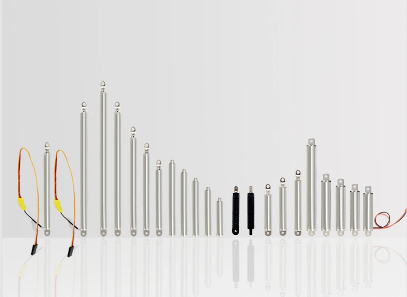
KT0805 standard model shown as a reference. The final interface is set on your approved drawing.
01 / Select a base model
Choose the body first, then define the change
The listed strokes and voltages provide a starting point. Force, speed, closed length, mounting clearance, end protection, and any stroke outside the listed set must be checked against the exact configuration. A longer stroke can change both the closed length and mounting locations.
| Base model | Tube / rod OD | Listed strokes (mm) | Voltage | Explore a reference |
|---|---|---|---|---|
| KT0805 | 8 / 5 mm | 30 / 50 / 80 / 100 / 120 | 5 V | 100 mm KT0805 |
| KT0905 | 9 / 5 mm | 10 / 15 / 20 / 25 / 30 | 5 V | KT0905 series |
| KTP0905 | 9 / 5 mm | 10 / 15 / 20 / 25 / 30 | 5 V | KTP0905 series |
| KT10-0905 / KT10-0903 | 9 / 5 or 9 / 3 mm | 10 | 5 V | KT10 reference |
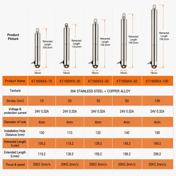
| KT1610 | 16 / 10 mm | 10 / 20 / 30 / 50 / 100 | 12 V / 24 V | 100 mm KT1610 |
| KT1609XX | 16 / 9 mm | 10 / 20 / 30 / 50 / 100 | 24 V | 24 V tubular model |
| KT1359 | 13.5 / 9 mm | 10 / 15 / 20 / 25 / 30 / 50 / 75 / 100 | 12 V | Built-in limit model |
Need a stroke beyond the listed values? Tell us the load, stroke, available closed length, and operating frequency. We will assess a modified version or another base model rather than quote a maximum without the full mechanism.
02 / Interfaces & options
Fit the actuator to the mating part
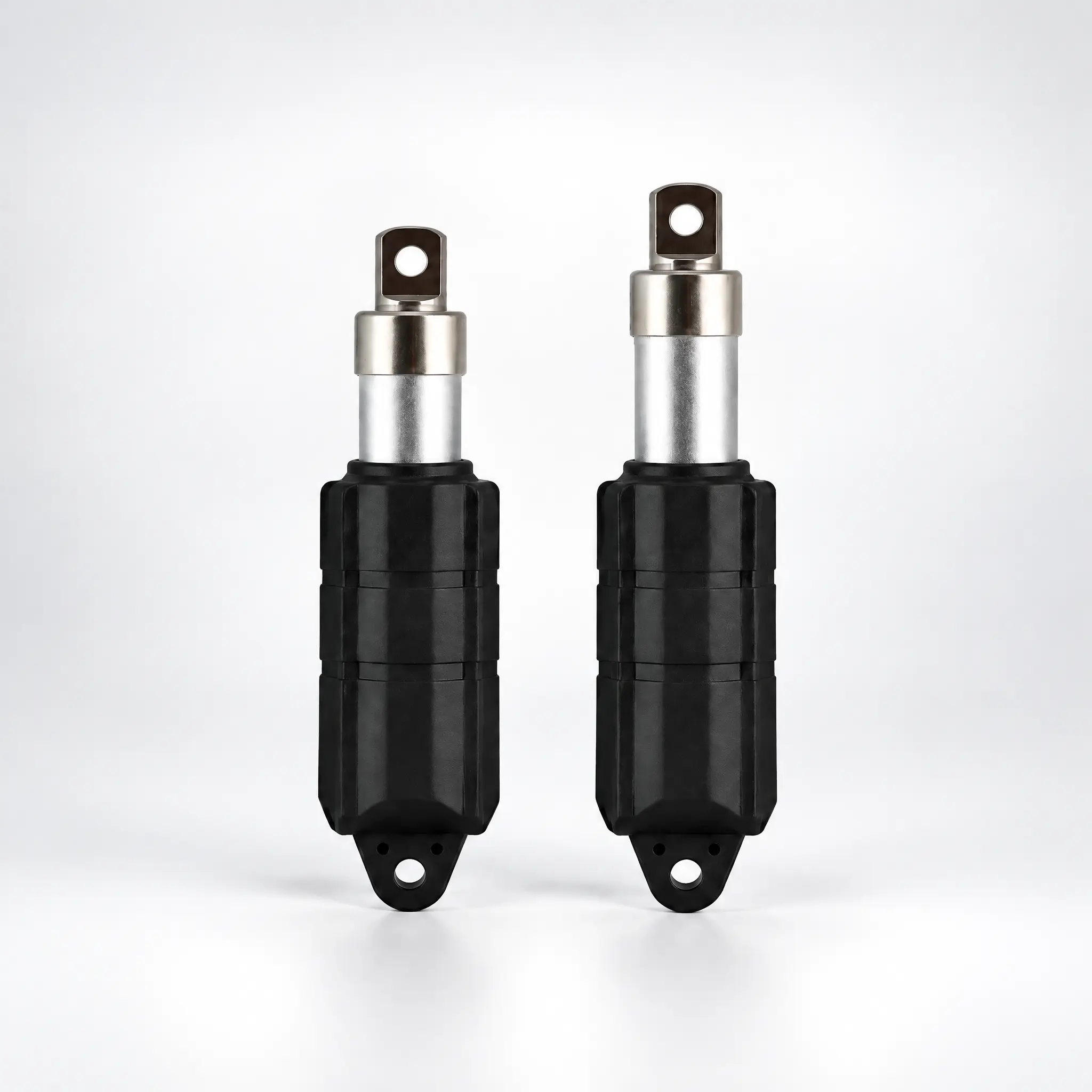
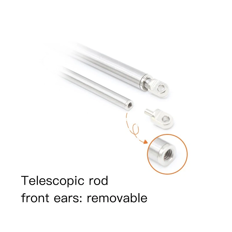
Use the standard model as a mechanical starting point. The approved outline drawing should settle the interfaces below before a prototype is made.
03 / Applications
Start with the movement in your device
The device sets the real load, space, stroke, and end protection. Choose the closest application, then bring its mechanism drawing to the review.
Electronics & smart home
Hidden panels and latch releases: check cover clearance, resistance, noise, and power.
Explore smart home actuators →Laboratory equipment
Sample trays and test fixtures: show guided load, closed length, and cleaning access.
Explore laboratory actuators →Portable medical equipment
Auxiliary covers: review the part and documents against its specific intended use.
Explore portable medical actuators →Vents & louvers
Small vents and dampers: check linkage geometry, sealing force, and duty frequency.
Explore vent and louver actuators →
04 / Engineering review
Send what you have. We will define the rest.
Any one of these is enough for an initial engineering review. The result is a clear model direction and a short list of what still needs to be decided.
01 / Drawing or CAD view
Mark the mounting points, available depth, travel, and moving part. We identify a suitable base model and the open dimensions.
02 / Sample or dimensioned photo
Show a scale and both end positions. We identify what must be measured before creating an outline drawing.
03 / Short requirement list
Share the device, voltage, stroke, load, and expected quantity. We identify a likely platform and quotation inputs.
What we return
A base-model recommendation, the key fit or performance questions, and a component outline for approval when the configuration is ready.
What needs your device drawing
Housing interference, guided loading, system-level safety, and certification depend on your complete mechanism. We check the actuator interface with you.
Have a complete drawing for build-to-print? See OEM actuator build-to-print projects. Prefer a checklist? Request the custom actuator requirement form. You can submit a drawing through the inquiry page today.
05 / Project route
From drawing to a repeatable part
The first review determines which standard model is closest and what the modification changes. A sample only moves to production after you approve the agreed configuration.
Review the requirement
We check the drawing or sample, load, space, and expected use; open inputs are returned together.
Confirm the configuration
We compare model, stroke, interfaces, lead wire, protection, and any new tooling with you.
Quote and prototype
The quotation records the approved configuration and sample, tooling, and inspection scope. A prototype is checked against that scope.
Approve and release
You evaluate the sample in your device; changes are captured on the drawing before the approved version is released for repeat orders.
Start your project
Send the mechanism, not just a part number
Attach a drawing, an annotated photo, or a sample description. Include the movement, target stroke, load or resistance, voltage, space, and estimated volume if you have them. We will review the base model and tell you what else is needed to evaluate a custom version.
Email: sale8@kabasi.cn · Ask for an NDA before sharing confidential files if your project requires one.
FAQ
Q: What Is The Longest Stroke You Can Make?
A: It depends on the model, load, and closed-length allowance. KT1610 reference configurations list standard strokes to 100 mm, with longer versions reviewed to 150 mm on request. For other platforms, send the required travel and available envelope so we can confirm the current drawing before quoting a limit.
Q: Can You Make An M4 Or M5 Front-End Thread?
A: M4 and M5 are shown as options on a KT0805 reference. Send your mating-part drawing, thread depth, and load direction so we can confirm the option for your selected model.
Q: Can We Start With A Sample Rather Than A Drawing?
A: Yes. A sample or dimensioned photo can start the assessment. We measure or review the interfaces, agree on a production drawing, and make the approved drawing the reference for prototypes and repeat orders.
Q: Will The Actuator Hold Position After Power Is Removed?
A: Holding force varies by model and configuration. Tell us whether the load is vertical, whether it can back-drive the mechanism, and how long it must hold; we will check the specific model rather than assume all versions behave alike.
Q: Is This An ODM Or OEM Project?
A: Most modifications start as ODM work on an existing KABASI platform. Build-to-print production against your complete drawing is reviewed separately as an OEM project. Drawing ownership, tooling, and confidentiality are recorded in the project agreement.