





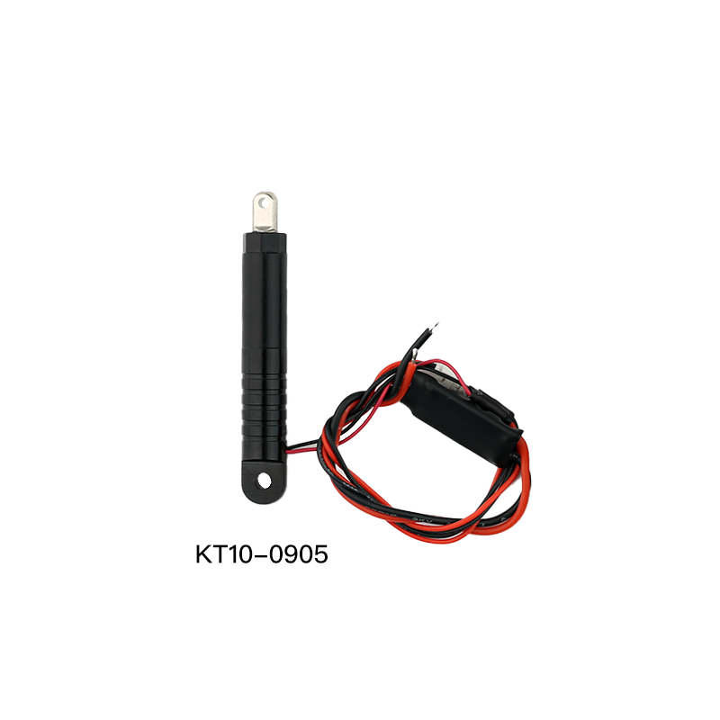

Micro Linear Motor
Product model: KT10-0905L
Product material: 7075 aluminum alloy + Hpd-59 brass
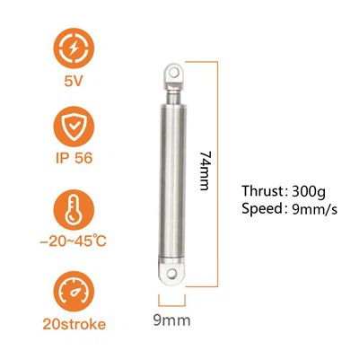
Stroke: 10mm (customizable)
Total length: 61mm
Push-pull force: 2.0KG/2N
No-load push-pull speed: 2mm/s
Protection current: 0.2A
Rated voltage: 5V
Noise: ≤50dB
Protection level: IP56
Self-locking force: greater than 10KG/100N
Product Introduction
A micro linear motor in this size class answers one question: can a short push be held after the power goes off. KT10-0905L moves at 2 mm/s no-load and 1.4 mm/s under its 2 kg load, so a full 10 mm stroke takes about five seconds, or seven with the mechanism resisting, and the rod stays where it stopped without a second lock. Supply is 5 V DC at a protection current of 0.2 A, which the device's own logic rail can carry.
The dimensions decide whether it fits. The outer tube is Ø9.0 mm, the rod Ø5.0 mm, the body 61 mm retracted and 71 mm fully extended. Stroke starts at 10 mm and can be extended to a drawing, with the head thread and the cable exit direction set at order. The housing is anodised 7075 aluminium alloy, the drive parts Hpb-59 brass, the rating IP56 and the running noise 50 dB or less.
Product Parameters
| Item | Specification |
|---|---|
| Model | KT10-0905L |
| Rated voltage | 5 V DC |
| Protection current | 0.2 A |
| Push-pull force | 2.0 kg (approx. 20 N) |
| No-load speed | 2 mm/s |
| Full-load speed | 1.4 mm/s |
| Stroke | 10 mm (longer on drawing) |
| Length retracted | 61 mm |
| Length fully extended | 71 mm |
| Tube / rod diameter | Ø9.0 mm / Ø5.0 mm |
| Holding force | above 10 kg (static) |
| Body material | 7075 aluminium alloy + Hpb-59 brass |
| Protection | IP56 |
| Noise | 50 dB or less |
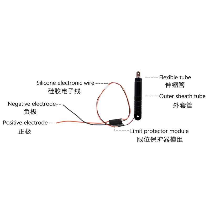
| End of stroke | external limit board cuts the motor |
| Duty | 10%, continuous cycling not advised |
Product Features
2 kg from a Ø9.0 mm tube
The body drops into a 10 mm slot and still pushes 2.0 kg, enough to compress a gasket, seat a latch bolt or move a small slide without a lever between the rod and the load.
Holds position with power off
Static holding force is above 10 kg. The rod stays where it was left through shutdown, packing and storage, so the mechanism does not creep back open.
Slow closure, no impact
At 2 mm/s no-load and 1.4 mm/s under load the rod arrives at constant speed and stops without a strike. Thin sheet, acrylic and optical parts take the load without marking.
Runs from a 5 V logic rail
Rated 5 V DC with a 0.2 A protection current, so the machine's own 5 V branch drives it. Two leads, polarity reversed for the opposite direction.
Automatic stop at both ends
The external limit board cuts power at each end of travel, so the mechanism cannot jam against a hard stop or run the motor stalled.
Anodised body, IP56 rated
7075 aluminium with an anodised finish and IP56 protection for inside or outside the machine frame; at 50 dB or less it is inaudible next to desktop equipment.
Device Fit: Desktop Laser Engraver Lid
An enclosure lid on a desktop laser engraver or marking machine needs a latch that closes tight and stays closed when the power drops. The lid has to press a gasket against the frame to keep smoke and dust inside, and it must not spring open when a job is interrupted. KT10-0905L mounts on the rear sheet-metal bracket with the rod facing the latch pocket on the lid, and the 10 mm stroke is the engagement depth.
Why it fits
- 10 mm matches the engagement on a thin lid: 3 mm acrylic, 2 mm of gasket compression and 5 mm of bolt engagement. It is enough to seal and not enough to bow the panel.
- 2.0 kg seats the gasket on a lid that closes under its own weight, so no spring or counterweight is added.
- 2 mm/s covers the stroke in about five seconds. The lid closes without a bang and without catching a finger.
- Holding force above 10 kg keeps the bolt extended through a power cut, an emergency stop or an unplugged machine, so smoke and stray reflections stay under the cover.
- 0.2 A at 5 V comes off the machine's 5 V rail; no 24 V supply and no driver board are added.
- The Ø9.0 mm tube fits a 10 mm folded lip in the bracket, and at 61 mm retracted it occupies a short run of the frame.
Space to leave in the build 61 mm retracted, 71 mm extended - the bolt adds 10 mm of travel forward. Leave 75 mm of straight space inside the bracket and a bend radius of at least five cable diameters at the exit.
Replacing the Existing Drive
| Item | KT10-0905L | Pull solenoid | Micro servo + linkage | Mini air cylinder |
|---|---|---|---|---|
| Holds position with power off | ✓ (above 10 kg) | ✗ (needs continuous power) | △ (depends on gearing) | ✗ (returns on release) |
| Stops at any point in stroke | ✓ | ✗ (in and out only) | ✓ | △ (needs a stop block) |
| No air supply, no driver board | ✓ (two leads) | ✓ | △ (needs PWM signal) | ✗ (pump and valve) |
| Driven from 5 V | ✓ | △ (mostly 12/24 V) | △ (mostly 6–7.4 V) | ✗ |
| Arrival without impact | ✓ (2 mm/s) | ✗ (audible pull-in) | △ | ✗ (end-stroke strike) |
| 2 kg class force | ✓ | △ | △ | ✓ |
| Ø9 × 61 mm envelope | ✓ | △ | ✗ (servo body plus linkage) | ✗ |
Model Selection
| Item | KT10-0905L | KT10-0905H | KT10-0903L |
|---|---|---|---|
| Push-pull force | 2.0 kg | 0.3 kg | 2.0 kg |
| No-load speed | 2 mm/s | 9 mm/s | 2 mm/s |
| Full-load speed | 1.4 mm/s | 6 mm/s | 1.4 mm/s |
| Time for 10 mm, no load | 5 s | 1.1 s | 5 s |
| Rod diameter | Ø5.0 mm | Ø5.0 mm | Ø3.0 mm |
| Holds position with power off | ✓ | ✓ | ✓ |
| Compressing or holding under load | ✓ | ✗ | ✓ |
| Fast travel with a light load | ✗ | ✓ | ✗ |
| Tight clearance at the head | △ | △ | ✓ |
Customization
| tion | Range | Needed at order |
|---|---|---|
| Stroke | from 10 mm, extended to drawing | target stroke, allowed retracted length |
| Thread | head and rod-end thread cut to the mating part | thread size, pitch, usable thread length, mating material |
| Bottom cable exit | cable leaves at the bottom (rear) end, direction and length set to the housing | exit direction, cable length, terminal type, routing space |
Certification and Test Equipment
The product is built under an ISO 9001:2015 quality management system, and the unit carries CE, RoHS, CCC and TUV certification; certificates are listed on the certification page. Production is sampled on six test stations: DC low-resistance tester, wire bending tester, quadratic element measuring instrument, insertion and extraction force tester, insulation resistance tester and salt spray chamber. The equipment list is on Testing Equipments. The factory has run in Xiamen since 2015, with the linear actuator division set up in 2021 to build new sizes to customer drawings; see About Us.
frequently question and answer
Q: Is 10 mm of engagement enough for an enclosure latch?
A: Work it out from the lid: 3 mm acrylic, 2 mm of gasket compression, 5 mm of bolt engagement. If the gap between lid and frame varies by more than 4 mm, take a 15 mm stroke, or engagement ends up shallow.
Q: The lid is heavy. Can it push the rod back?
A: Static holding force is above 10 kg, so lid weight on the rod end will not drive it back below that value. With the rod pointing down, the load hanging on it counts against the same 10 kg; above that, add mechanical support.
Q: What happens if the bolt jams against the lid?
A: The limit board is set at a 0.2 A protection current, so the current rises to that value and the motor is cut instead of stalling and heating. Find and clear the jam first; the board is not meant to hold against a dead stop.
Q: Can it stop halfway through the stroke?
A: Yes, and it holds there. Force does not change with position - 2.0 kg is fixed for this model - and a mechanical stop block is the more reliable way to set a shallower engagement.
Q: Does it stay powered while the lid is closed?
A: No. Power is cut after the 5 s stroke and the bolt holds on its own. No standing current means no standing heat inside an enclosure.
Q: Two units, one on each side - how is the 5 V shared?
A: Wire both in parallel on the same 5 V rail, allowing 0.2 A each and 0.4 A in total. Each keeps its own two leads for direction; a shared thin line drops voltage when both move at once.
Selection and Quotation
Send stroke, load, mounting space, supply voltage and cable exit direction, and a model with a confirmed drawing comes back within 24 hours. A first article can be built to the custom specification before the batch.
Hot Tags: micro linear motor, China micro linear motor manufacturers, suppliers, factory, 12v micro linear actuator, micro actuator servo, micro piezoelectric actuator, micro linear stepper motor, micro electric cylinder, Micro Electric Actuator
Previous
Micro Electric ActuatorNext
No InformationYou Might Also Like


Send Inquiry