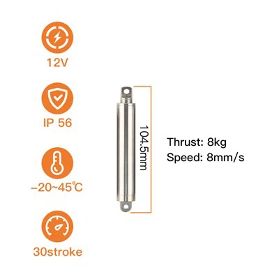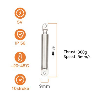
If you’re working with linear motion systems, you’ve probably asked this question at some point: What is the input signal range for a 24V actuator? As a supplier of linear actuators, I get dozens of these inquiries every week—from industrial equipment builders to DIY enthusiasts and automotive repair shops. The truth is, the answer isn’t as straightforward as just “24 volts.” It depends on a mix of factors that go beyond the basic voltage rating, and getting it right makes all the difference between a smoothly running system and one that stalls, overheats, or fails prematurely. Let’s break this down, share what we’ve learned as a 24V actuator supplier, and clear up the common confusion around input signals for these components.
First, let’s start with the basics. A 24V linear actuator is designed to operate on direct current (DC) power, which is why our Linear Actuator 24V page outlines this specific voltage as the core specification. Unlike alternating current (AC) actuators, which run on fluctuating power that cycles from positive to negative, DC actuators rely on a steady flow of current in one direction. That consistency is why they’re so popular for applications that need precise, controlled motion—think medical beds, agricultural equipment, or automated gate systems. But here’s the thing: the “24V” label doesn’t mean you have to feed exactly 24.0 volts into the actuator. The input signal range is actually a window, and staying within that window is critical for performance and longevity.
So, what is that window? From our years of engineering and testing, the typical input signal range for a standard 24V actuator is 18V DC to 30V DC. Wait, that might seem wide—why such a big gap? Let’s explain. Actuators have internal motors, gears, and electronic components (like H-bridges for direction control) that can handle some variance, but there are limits. If you drop below 18V, the motor won’t generate enough torque to move the load. We’ve seen customers try to power a high-load 24V actuator with a 12V battery, and the result is often a unit that whirs but never extends—because the voltage is too low to overcome the friction in the gears or the weight of the load. On the flip side, going above 30V is a risk. The extra voltage pushes more current through the motor windings, leading to overheating, premature wear on the brushes (if it’s a brushed model), and even permanent damage to the internal electronics. We’ve had customers send back actuators that burned out because they connected a 36V power supply, and it’s always avoidable by sticking to the input range.
But here’s where things get nuanced: not all 24V actuators are the same. The input signal range can shift based on the actuator’s design, the type of motor it uses, and whether it has built-in control features. For example, our heavy-duty 24V industrial actuators (listed on our 24V Actuator page) might have a slightly narrower range—say 19V DC to 29V DC—because they’re built for consistent, high-load operation. Their motors are wound for optimal performance right around 24V, so deviating too far from that can impact their lifespan. On the other hand, our compact 24V actuators, designed for space-constrained applications (like adjustable standing desks or small medical devices), might handle a range from 17V DC to 31V DC, since they’re built for lower loads and more flexibility in power sources. That’s why it’s always important to check the specific datasheet for your actuator—generic answers can lead to mistakes.
A common point of confusion we hear from customers who also work with 12 Volt Dc Actuator models is how voltage translates to performance. If a 12V actuator has an input range of 9V to 15V, why does a 24V range start lower relative to its rated voltage? It’s all about the motor’s design. A 24V motor has thinner wire windings than a 12V motor (since higher voltage means less current for the same power), so those windings are more sensitive to overvoltage. The 12V motor’s thicker windings can handle more variance, which is why our 12V Actuator Motor page notes a wider operating range. That’s a key distinction—voltage isn’t just a doubled number when you move from 12V to 24V; it changes how the motor interacts with the power supply.
Let’s talk about what happens when you operate outside the input range, because that’s where the real-world impact shows. When voltage is too low, the motor can’t reach its required rotational speed, so the actuator moves slowly, or not at all. Over time, this causes the motor to draw more current than it’s rated for (a phenomenon called “locked rotor current”), which overheats the windings. Even if you only run it at low voltage occasionally, it shortens the actuator’s lifespan. On the high end, overvoltage causes the motor to spin faster than designed, which puts extra stress on the gears and seals. We’ve seen actuators that were run on 32V for a few months fail because the gear teeth stripped, and the owner had no idea the power supply was exceeding the rated range. It’s a preventable issue with the right knowledge.
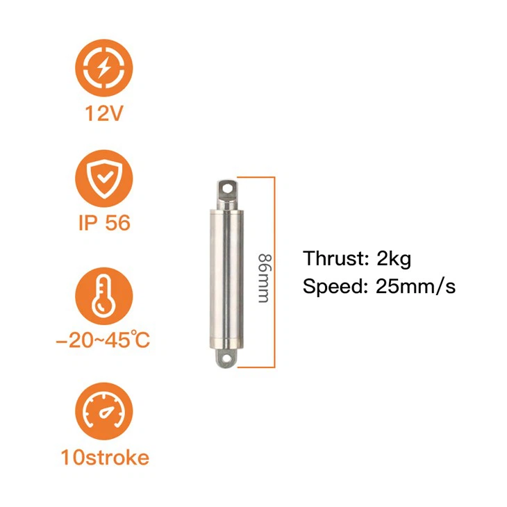

Now, how do you determine the right input signal range for your specific 24V actuator? The first step is to check the manufacturer’s documentation (that’s us, by the way—we include this info on every product page, like our Linear Actuator 24V page). If you don’t have the datasheet, there are a few field tests you can do, but proceed with caution. Start with a known 24V power supply and measure the actual voltage at the actuator’s terminals (not just the power supply’s output—long cables can cause voltage drop). Then, gradually adjust the voltage down and see where the actuator stops moving smoothly; that’s your lower limit. Gradually adjust up until you notice unusual noise or overheating; that’s your upper limit. But always stay conservative—don’t push the edges, because even if it works temporarily, it’s not good for the actuator.
Another important factor is the type of power supply you’re using. Most 24V actuators work best with a regulated DC power supply, which maintains a consistent output within the input range. Unregulated supplies can have voltage spikes or drops, especially under load, which can push the actuator outside its safe range. For example, if you’re powering an actuator from a car battery (a common setup for off-road or RV applications), the battery’s voltage will fluctuate as it charges and discharges—from around 21V when fully charged to 12V when almost dead (wait, no—actually, a 24V battery bank will range from about 25.2V when full to 21V when depleted). That’s why our automotive-grade 24V Actuator models are designed to handle that 21V to 26V range, which fits within our standard input window and accounts for battery variability. It’s a small design detail that makes all the difference for mobile applications.
Let’s touch on signal quality, too—this is something that’s often overlooked, especially by first-time users. The “input signal” isn’t just about voltage level; it’s about stability and whether the signal is pure DC. If your power supply has a lot of ripple (small fluctuations in voltage), that can cause the actuator to shudder or operate erratically, even if the average voltage is within the range. For applications that need precise control (like robotics or medical devices), we recommend adding a capacitor to smooth out the signal. That’s a tip we share with every customer who reaches out about optimizing their actuator’s performance, and it’s one of the most common ways to fix issues that people blame on the input range.
Now, let’s compare this to 12V actuators, since many customers switch between the two. Our Compact 12V Linear Actuator line has an input range of 9V to 15V, which is about 75% of the rated voltage on the low end and 125% on the high end. For our 24V actuators, that’s about 75% of rated voltage on the low end (18V) and 125% on the high end (30V)—the same ratio! That’s not a coincidence. Engineers design the input range to be consistent relative to the rated voltage, so whether you’re working with 12V or 24V, you’re looking at a 6V window around the core rating. That consistency makes it easy to remember, as long as you apply it to the right voltage.
We’ve had customers come to us after buying a cheap 24V actuator online, confused because their unit stops working after a few weeks. A lot of those off-brand actuators cut corners on motor winding quality and internal protection circuits, so their input range is much narrower—sometimes just 23V to 25V. That means even a small voltage fluctuation from a cheap power supply will kill the unit. That’s why we always recommend working with a reputable supplier like us, where every 24V Actuator goes through testing to confirm its input range before it leaves our warehouse. We include that test data in the product documentation, so you never have to guess.
So, to wrap up what we’ve learned as a 24V actuator supplier: the standard input signal range is 18V DC to 30V DC, but this can vary based on the actuator’s design, load capacity, and intended application. Always check the specific datasheet for your model, use a regulated power supply, and avoid pushing the voltage to the extremes to keep your actuator running smoothly. Whether you’re a large industrial integrator or a hobbyist building a custom project, understanding this range is key to getting reliable performance from your linear actuator.
If you have more questions about input signals, specific actuator models, or need help selecting the right unit for your application, feel free to reach out to our team. We’ve spent years working with linear actuators, and we’re happy to share our expertise to make sure your project runs without hiccups.
References
- Linear Actuator Technical Standards for DC Motor Operation, International Electrotechnical Commission (IEC) 60034-1
- Actuator Power Supply Compatibility Guidelines, Motion Control Association (MCA)
- Design and Testing of Linear Actuator Input Ranges, AB Engineering Department, 2024